Structural pipe design according to AWWA M55
- Introduction
In accordance with the different norms and standards, the pipes must be selected in accordance with their class of nominal ring stiffness (SN), as SN2, SN4, SN8 or SN16 (in accordance with the standard ISO9969), or in accordance with any other stiffness standard (DIN 16961, ASTM F894, NBR 7373 etc.) notwithstanding the testing methods (at constant speed or constant load). For an example, a project requires pipe stiffness of 5.5 and the nearby standard value is that of pipe stiffness 8 and hence engineer could only provide details of profile with stiffness 8.
In addition to this and in accordance with article 9.1 of the standard EN 13476-3, the manufacturers are allowed to produce pipes that fall between the above listed SN-classes. To qualify for this admission the producer must be able to prove this solution with static calculations. With Krah pipes, are able to provide any project with pipes of the precise stiffness that the project demands.
It is useful to perform static calculations for pipes taking into consideration the specifications of each particular project. In 99% of cases the pipes selected for a particular project are over dimensioned in the original project design documentation. Using the calculations, it is possible to prove that it is sufficient to install a pipe with less stiffness but the correct profile, including the required safety factor which is also cost-efficient and faster to install.
The ATV A127, a German standard for static calculations for all kind of pipes is widely spread and used in the European region. It latest version dates from the year 2000. The software used by Krah was provided by IngSoft and is called Easypipe.
Globally, a different design manual is used for static calculations of flexible polyethylene pipes published by the American Water Works Association called M55 PE – pipe design and installation. Therefore, the Krah group developed a new software in Mickey for static calculations called structural pipe design according to AWWA M55. Static calculations according to AWWA M55 don’t need many parameters and information. It is user-friendly and easy to use.
The following chapters of this article will explain which input data is needed and which formulas are necessary to analyse, if a buried pipe verifies.
- Input data
First of all, it is necessary to define the pipe which shall be calculated. Mickey is linked to the Krah pipe database. By choosing the diameter and the material (e.g. PE80/100), all information which are necessary for the calculation will be automatically transferred to Mickey.
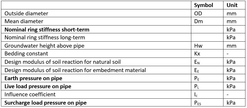
To calculate the nominal pipe stiffness (short-/long-term) the following parameters are needed:
![]()
Where:
E = short-/long -term modulus of elasticity of pipe material [kPa]I = moment of inertia [mm4/mm], directly calculated by Mickey
Dm = mean diameter
A special feature in Mickey is, if one only knows the diameter of the pipe, but is unsure about the size of profile type, Mickey is able to calculate the best suitable pipe for installation under the given circumstances.
Secondly, it is necessary to define the specifications about the Trench and the details of the Installation of the pipe. Needed Input e.g. is Cover height, Trench width, Bedding Angle, soil type etc. To define the earth load pressure ( on the pipe, this input is necessary.
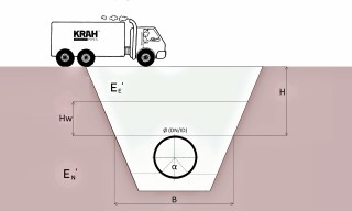
Fig. 2: Sketch for installation and trench and a schematic load above the pipe
Where:
Hw = groundwater height above pipe [m]H = depth of cover [m]B = trench width [m]α = bedding angle [°]EN’ = design modulus of soil reaction for natural soil [kPa]EE’ = design modulus of soil reaction for embedment material [kPa]
The earth pressure on the pipe is, = ρ H [kPa]
Where:
ρ = soil saturated unit weight [kN/m3]
Thirdly one should define what kind of loads exist over the buried pipe to determine the live loads ( . The AWWA has several types pre-defined and are integrated in Mickey e.g. no traffic, normal highway traffic etc. Also, the type of pavement is necessary to define e.g. rigid, flexible or non.
Furthermore, details about the static loads are needed before starting calculating. One should define the existing surcharge loads and the load area length at each side of the pipe. A surcharge load is any load which is imposed upon the surface of the soil close enough to the excavation to cause a lateral pressure to act on the system in addition to the basic earth pressure. Groundwater will also cause an additional pressure, but it is not a surcharge load.
The surcharge load is ![]()
Where:
I_c = influence coefficient from table 5-5 AWWA M55 and Fig. 5-2
W_s= distributed surcharge pressure acting over ground surface [kPa]
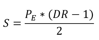
The AWWA M55 recommends using an allowable ring deflection of 7.5%. In comparison, the German ATV A127 calculates with an allowable ring deflection of 6%. Buckling safety factor (FSp) and hoop compression safety factor (Fsc) are both 2, to ensure enough safety for the static calculation.
- Calculations
In the first instance, intermediate results are calculated, because they are necessary for the final results. The figure below shows the intermediate results calculated by Mickey.
Tab. 1: Intermediate Results calc. by Mickey
The calculated figures above are needed for the final results and to check if the chosen pipe verifies the loads and is suitable for installation.
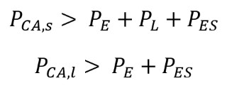
For giving a Statement if the Pipe is suitable for Installation, the following indicators have to be calculated and determined. For a conservative design, the pipe must be within its safe allowable limit for each of these three reactions – deflection, buckling and ring compression.
- Percent ring deflection:
Ring deflection is an essential response of flexible pipes to soil load. Deflection promotes arching, allows the pipe to shed load and develops supporting reactions in the surrounding soil. To calculate ring deflection according AWWA M55, Spangler’s modified Iowa formula is used:
![]()
Where:
T_L = time - lag factor
E = short-term modulus of elasticity of pipe material [kPa]DR = dimension ratio, OD/s1
E'= modulus of soil reaction [kPa]
The calculated percentage of ring deflection must be smaller than the allowable percent ring deflection of 7,5%.
- Allowable short - / long – term external pressure (buckling)
When buried pipes are subjected to external loads such as negative internal pressure, groundwater or extremely high earth loads, an instability can occur in the pipe wall that may lead to large inward deformations called buckling.
Allowable short – term external pressure:
![]()
Where:
N = safety factor 2,0
R_w = buoyancy reduction factor (Eq. 5-11 AWWA M55)
B' = soil elastic support Factor (Eq. 5-12 AWWA M55)
The allowable long – term external pressure ( is calculated equivalently to the allowable short – term external pressure with the only difference of using the long-term modulus of elasticity of the pipe material.
To give a statement if the buried pipe can withstand buckling, the allowable external pressure must be greater than the summation of external loads applied to the pipe.
- Wall compressive stress
The earth pressure applied to a buried pipe creates a compressive thrust stress in the pipe wall. When pipelines are pressurized, the compressive stress is usually cancelled by the tensile thrust stresses form pressurization.
The compressive wall stress should be kept less than the allowable compressive stress of the material. A pipe is verified if the above requirements are fulfilled.
- Conclusion
The use of an own structural engineering calculation allows a neutral and realistic assessment of project specific conditions. As a pipe manufacturer and supplier, you will be able to determine important dimensions quickly and the economical projection can be carried out precisely. It is also possible to export the calculations as a PDF file and use it for documentation of a project and also present the results to the customer. Mickey offers diversity and flexibility by considering the latest standards. Experts of the Krah team are also in the most important standard committees and therefore internationalism is ensured.
The PE pipe design and installation manual (M55), seems to be an easy approach, which is sufficient in most cases. For a more detailed solution, the finite element method or the ATV A127 can be used.
Author:
Hussein Tahmaz
KAT Gmbh
