Sewage treatment plant Karlsruhe
Project report by FRANK GmbH, Germany
Welded large-diameter pipes made of PE 100 in sewage treatment plant construction - new adsorption building - pressure pipes up to DN/ID 1200 and coiled pipes up to DN 2000 with electrofusion welding
Stadtentwässerung Karlsruhe has been operating the central sewage treatment plant for over 100 years, starting in 1913 with a first screening plant. The location was determined in 1908 - at that time, the Baden Grand Ducal Administration commissioned the city to mechanically clean the wastewater from the city area before discharging it into the Rhine. The choice of a location as low as possible, close to the boundary of the Rhine district, allows the wastewater to flow out of the city districts mainly in a free gradient. The catchment area of Stadtentwässerung Karlsruhe covers 4586 ha. The network length in 2009 was 1108 km. The annual inflow to the sewage treatment plant from 2004 to 2009 was approx. 34,000,000 m³ - the design flow rates for the sewage treatment plant are 2.1 m³/s in dry weather and 4.0 m³/s in rainy weather. [1]
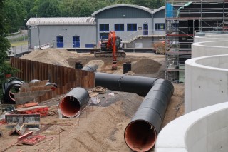
Fig. 1: Overview of the construction project, contact and sedimentation basin with connecting pipes made of PE 100
Presentation of the construction project:
In order to be able to safely and stably comply with the legally required effluent values, the construction of a fourth purification plant, consisting of a filtration plant for the retention of fine particles and an activated carbon plant, was completed. After completion of the filtration plant, construction of the activated carbon adsorption plant began in 2019. In addition to further improving the effluent values, the adsorption plant will also reduce so-called trace substances. These trace substances, such as medication residues or hormone substances, cannot be treated or removed from the effluent of a wastewater treatment plant with the current state of wastewater treatment. The new adsorption stage contains six contact basins, each with a capacity of approximately 1,870 m³. Here, powdered activated carbon is added to the biologically purified wastewater so that the trace substances still dissolved in the wastewater are bound. The waste water mixed with activated carbon then enters a sedimentation basin with a capacity of 8,200 cubic metres. Here, the activated carbon is separated from the waste water and returned to the process. Some of the loaded activated carbon is discharged from the process and incinerated with the sewage sludge at the plant. The pre-treated effluent is passed through the sand filtration system to remove the final residuals and is discharged into the treatment plant effluent. [2]The six contact basins, the two sedimentation basins as well as a pumping station and several shafts were constructed by Wolff & Müller using in-situ concrete. The connecting pipes between the structures were constructed as PE100 pipelines buried in the ground with welded pipe joints.The engineering office Tuttahs und Meyer (Aachen / Bochum), which was responsible for the planning and tendering of the construction project, planned the following PE 100 pipes for the connecting pipes of the individual structures.
Outlet filtration in contact basins:
- Wound pipes made of PE 100 according to DIN EN 16961 DN 2000 with closed base and cover layer, ring stiffness SN 8, pipe connection with integrated heating coil socket.
Return flow from sedimentation into filtration:
- Wound pipes made of PE 100 as before, but in nominal size DN 1600
Outlet contact basin in sedimentation (incl inlet siphon) and outlet sedimentation:
- Pressure pipes of PE 100 according to DIN EN 8074/75 DN/ID 1200, SDR 17, pipe connection on site by means of heating coil sockets - Pipe connection of the prefabricated pipe elements by means of heating element butt welding
Return coal siphon from sedimentation as well as inlet contact basin from the return coal pumping station
- Pressure pipes made of PE 100 as before, but in nominal diameter DN/ID 900, SDR 17
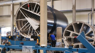
Fig. 2: Production of wound pipes on a Krah machine at FRANK Kunststofftechnik GmbH
Pipe material and manufacture of the coiled pipes according to DIN EN 16961:
The production of the profiled DN 1600 and DN 2000 sewer pipes made of PE 100 with integrated heating coil socket as well as the manholes and components was carried out at FRANK Kunststofftechnik GmbH in Wölfersheim, Hesse.
BorSafeTM HE3490-LS black was used as the PE 100 pipe material. Here are some selected material characteristics:
- Density 959 kg/m³ according to ISO
1183 - Melt flow index 0.25 g/10 min
according to ISO 1133
- Tensile stress 250 N/mm² - short time
according to ISO 527-2 - Modulus of elasticity 1100 N/mm² - short
time according to ISO 527-2
Polyethylene (PE 100) is a thermoplastic which, in addition to a low specific weight, also has excellent processability, weldability and formability. Polyethylene is particularly resistant to aggressive media (acids and alkalis). Furthermore, the molecular structure of the material, which is composed of carbon and hydrogen, enables it to be recycled. Polyethylene is 100 % recyclable. For pipes made of PE (100), the proof of long-term strength („durability“) is already mentioned in the basic standard. DIN 8074, Pipes made of polyethylene (PE) - PE 80, PE 100 - Dimensions and DIN 8075, Pipes made of polyethylene (PE) - PE 80, PE 100 - General quality requirements, tests contain the following statement on long-term strength:
„The service life previously estimated at 50 years can be extended to at least 100 years of service life for PE pipes at application temperatures of 20°C on the basis of many years of tests and experience.“ [3]
This ensures that PE100 pipes and fittings are a durable and sustainable solution for transporting wastewater (and other liquid media) over an economically, assured depreciation period of up to 100 years.
Production of coiled pipes:
The PE 100 moulding compound is wound in the molten state as a continuous, overlapping strip in a spiral on a metal drum. (Fig. 2) An additional, functional and/or inspection-friendly inner layer can be applied via a coextruder. A metal drum serves as calibration, which determines the inner diameter (DN) of the pipe. The pipes are cooled slowly by a blower. In this way, residual stresses caused by volume shrinkage and the production process can be reduced.
By winding several layers of the moulding compound on top of each other and varying the amount of material applied, different wall thicknesses and profile geometries can be produced. (Fig. 3) PKS® sewer pipes are available in nominal sizes DN 500 to DN 3500. The base wall thickness is determined in accordance with the minimum requirements of DIN EN 13476-3 or operational requirements. Production and quality assurance are carried out within the framework of the general building authority approval Z-40.26-359.
Welded joints:
In the PKS® pipe system (profile duct pipe system), the individual pipes (but also manholes / components) are welded with the integrated heating coil socket (E-socket) as standard. During the manufacturing process, the socket and spigot end are formed onto the pipe. During installation on site, the spigot end is then inserted into the socket and subsequently welded. (Fig. 4) The welding parameters are transferred to the welding device via a barcode. The welding device automatically logs the welding process.
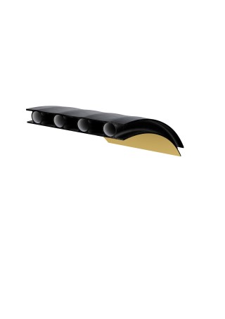
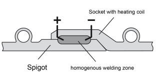
Fig. 3: Profiled sewer pipe with closed base and cover length - PKSplus
Fig. 4: Welded joint - schematic representation; integrated E-socket
Pipe material and manufacture of the pressure pipes according to DIN EN 8074/75:
The production of the pipes DN/ID 900 and DN/ID 1200, SDR 17 mm was carried out according to DIN 8074/75 in the Bad Hall plant of AGRU Kunststofftechnik GmbH. As with the coiled pipes, BorSafeTM HE3490-LS black was used as the pipe material. This is a bimodal PE 100. The material is particularly suitable for the production of large diameters, as it exhibits so-called „low sagging“ behaviour during manufacture. This means that the material in the plastic state within the nozzle and calibration has little tendency to flow downwards according to gravity. With materials whose properties are not optimised accordingly, it is not possible to produce uniform wall thicknesses with large pipe diameters (Fig. 5).
Production of the heating coil sleeves:
Up to a pipe diameter of 500 mm, the heating coil sleeves are manufactured at AGRU Kunststofftechnik GmbH, Bad Hall in a multi-stage injection moulding process. The „large“ heating coil sleeves (currently up to 1400 mm) are produced from thick-walled PE blanks. The PE blank is machined to size in a multi-axis machining centre. The heating coil is then „ploughed in“.
Prefabrication of piping components:
In order to facilitate the assembly of the pipes and components on site and to reduce the number of welded joints on site, pipe fittings were prefabricated from the pipes at the FRANK Kunststofftechnik GmbH factory. Care had to be taken to ensure that the components could still be transported and that installation in the excavation pit was still possible.
The welding processes used for the prefabrication were heated-tool butt welding (HS) and hot-gas extrusion welding (WE). After butt welding, the inner bead was removed while the pipe was still partially warm in order to obtain a smooth, homogeneous pipe surface on the inside - Fig. 6 and Fig. 7.
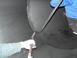
Fig. 6: Inner bead removal
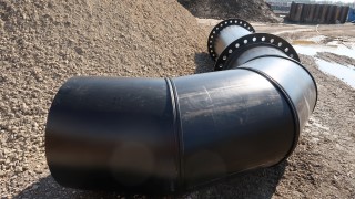
Fig. 7: Prefabricated pipe fitting DN/ID 1200mm
Installation of the pipes and welding of the joints:
From spring 2020 onwards, the pipes and fittings were installed in sections by van den Hooven Rohrleitungsbau in accordance with the construction schedule. The pipes were inserted into the prepared, shored excavations by means of a tower crane or hydraulic excavator and prepared for welding. The mechanical processing of the pipe surface (the peeling) was carried out on the 900 and 1200 mm pipes with a link peeling device from PF-Schweißtechnologie GmbH - Figure 8. Directly after peeling and cleaning the pipe surface, the heating coil sleeves were then pushed on and pulled onto the pipe end by chain hoists - Fig. 9.
Since the heating coil of the large E-muffs is designed as a so-called „bifilar“ coil (two separate welding zones), welding was carried out with two welding machines in parallel in order to keep the processing time as short as possible.
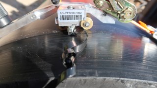
Fig. 8: Peeling of the pipe surface before electrofusion DN/ID 1200mm
Construction details:
The connection of the PE pipes to the concrete structures was made with a tension-resistant and watertight wall bushing. The „FRANK wall collar“ made of EPDM is used here as a sealing element between the concrete and the PE. The required tensile strength is generated by a welded-on, perforated plate collar. In order to be able to safely absorb the occurring forces of thermal expansion in the PE pipes, the component was mathematically designed for a max. temperature difference of 10 K in operation. In order to enable the DN 1600 and DN 2000 pipes to be walked on, DN 1000 tangential shafts were manufactured in the factory in a backwater-proof design. Since the two pipes are „overpressured“ during operation (approx. 0.50 bar), a corresponding DN 600 manhole cover was firmly screwed to the monolithic tangential manhole - Figure 10.
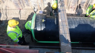
Fig. 9: Mounting the heating coil sleeve
To ensure an even inflow into the contact basins from the coal pumping station, flanged transitions from rectangular to round DN/ID 900 mm were manufactured in the factory from PE sheets and installed on site - Fig. 11.
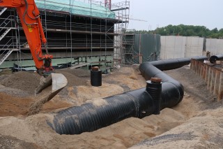
Fig. 10: Installation of sand in the pipeline zone
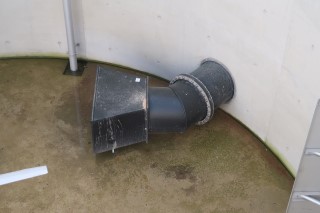
Fig. 11: Flanged transitions from rectangular to round DN/ID 900mm made of PE sheets
Installation of the pipes:
The DN 1600 and DN 2000 coiled pipes were installed on prepared supports under „dam conditions“ - the pipeline zone (bedding) was constructed entirely with sand - an add-on compactor was also used during installation and compaction. The construction management carried out load plate tests to determine the degree of compaction as part of the construction supervision - Fig. 12.
Conclusion
By choosing PE 100 as the pipe material, the construction project presented here could be completed economically and on schedule according to the state of the art. The flexible design and the high degree of prefabrication made it possible to install the pipes and fittings quickly and economically on site. Pipes and fittings made of environmentally friendly polyolefins (PE/PP) can be 100 % recycled after their useful life in just a few process steps: An ecological and economic advantage compared to systems made of conventional materials (e.g. composites), which have to be reprocessed after dismantling with high energy expenditure or disposed of at additional cost. A great advantage for the companies involved (Wolff & Müller as the executing contractor and van den Hooven as the pipeline builder) was that all pipes and fittings as well as the connection technology - heating coil socket, welding equipment and peeling equipment - were supplied or made available completely by FRANK GmbH. The instruction in the processing of the large heating spiral sleeves as well as the site supervision and assembly support were completely provided by FRANK GmbH. Necessary plastic assemblies and extrusion welding on site were also carried out by FRANK GmbH.
Bibliography & Details
[1] Brochure Civil Engineering Office
https://www.karlsruhe.de/b3/bauen/tiefbau/entwaesserung/klaerwerk/HF_sections/rightColumn/1553511441588/1553502666620/Tiefbauamt_Broschuere_2010_1.pdf
[2] https://www.karlsruhe.de/b3/bauen/tiefbau/entwaesserung/klaerwerk.de
[3] DIN EN 8074/75
[4] Agru Plastics Technology GmbH, Bad Hall
Scope of delivery
Pressure pipe PE 100:
- da 900, SDR 17 approx. 140 running metres
- da 1200, SDR 17 approx. 120 running metres
Each with pipe fittings and E-muffs.
Wound pipe PE 100:
- DN 2000, SN 8 approx. 80 linear metres
- DN 1600, SN 8 approx. 90 linear metres
Each with pipe fittings and integrated E-socket.
Partner
Planners:
IB Tuttahs und Meyer (Aachen / Bochum)
Construction:
Wolff & Müller Ingenieurbau GmbH
Pipeline construction:
van den Hooven Rohrleitungsbau GmbH
Your contact for further information:
This email address is being protected from spambots. You need JavaScript enabled to view it.
Jochen Obermayer
