Performance of PE pipes with glass fiber
M.Tokiyoshi1), H.Kudo1), M.Endo1), K.Inoue1)
N.Shibasaki2), T.Nakayama2), H.Matsukuma2), M.Kodera2)
Y.Niinomi3), M.Masuko3)
P.Vanspeybroeck4)
1)High stiffness Polyethylene Pipes Association, JAPAN
2)Tokyo Electric Power Company.,Inc , JAPAN
3)Tokyo Electric Power Service Company.,Ltd, JAPAN
4)BECETEL v.z.w , BELGIUM
Abstract
Polyethylene pipes are successful worldwide due to the superior performance (Flexibility, light weight, lifetime, tighten joint) for water and sewerage supply. However according to our ISO standard concerned Polyethylene pipes we have to use solid wall pipe with too thick against for internal pressure. The major job challenge involved finding new polyethylene solution with best high modulus and flexibility such as superior performance of polyethylene for world customers. In achieving this, polyethylene resin with glass fiber by spiral cross winding method take us new.
Our technical team should be considered a better option (characteristics of basic) not only those tests but also it was extra performance with proof of some analysis in Japan.
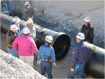 |
| Glass Fiber reinforced pipes on-site |
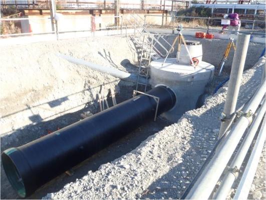 |
| Concrete edging |
Introduction
PE pipes have been successfully used for water distribution pipelines around world for many years. Those pipes are generally made with solid walls because of strong deflection of the pipe during terms of service. This is necessary to need over hundred mm thickness in case high internal pressure especially for large diameter pipe. This paper provides technical characteristics and discusses solid wall pipe applications with Polyethylene and Glass fiber. It combined high E-modulus and many benefits of polyethylene. HIPPA as High stiffness Polyethylene Pipes association established 1987 are operated by DAINIPPON PLASTICS, NIPPON HAWER, TORIIKASEI,
PRIME POLYMER and MITSUI CHEMICALS INDUSTRIAL PRODUCTS in Japan. We should know what we are those basically characteristics concerned Plastic piping systems made from glass fiber reinforced polyethylene (PE-GF) for water supply and for drainage and sewerage.
Basically characteristics
Our first approach was to examine what they have. Here is basically characteristics of PE-GF shown in Table 1.
| Table 1 Basically characteristics | |||
| Property | Test method | Unit | Value |
| Density | ISO 1183 | kg/m³ | 1.1 |
| Linear expansion coefficient | JIS K 7197 | - | 5.0 x 10⁻⁵ |
| Thermal conductivity | ASTM C 177 | W/mK | 0.37 |
| Oxidation induction time | ISO 11357-6 | min | 54 |
| Tensile strength at 20°C | ISO 6259-1, -3 | MPa | Circumferential: >40 Longitudinal: >24 |
| E-modulus | JIS K 7162 (ISO178) | MPa | Circumferential: >2,500 Longitudinal: >2,000 |
| Longitudinal reversion | ISO 2505-1, -2 | % | 0.25 |
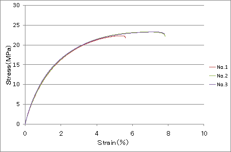
Our experimental results were indicated as follows.
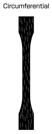
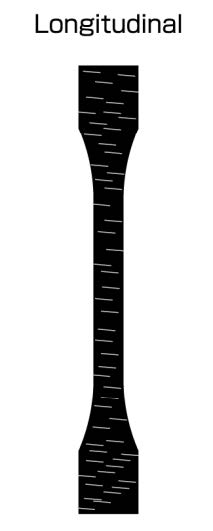
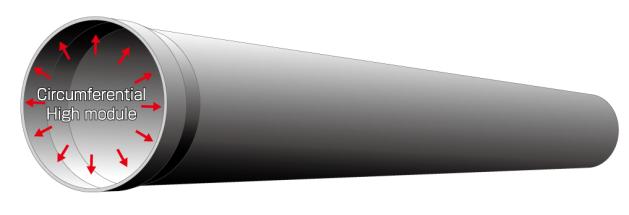
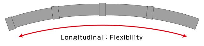
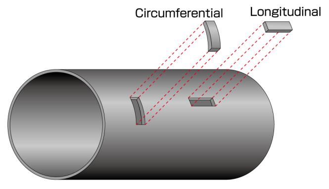 Fig. 1 Circumferential and longitudinal direction
- PE-GF has a specific gravity greater than that of seawater.
- PE-GF has a specific linear expansion coefficient smaller than that of PE100.
- It may be said that there was a big gap in the results of tensile strength and E-modulus between direction circumferential and longitudinal see Fig.1. Circumferential of PE-GF is more than twice as much that of PE100, although longitudinal of PE-GF is as same as that of PE100.
- It has high hoop stress as like GRP nevertheless flexibility for longitudinal direction as like polyethylene.
Practical applications
1. Reduction factors according to ISO 13761
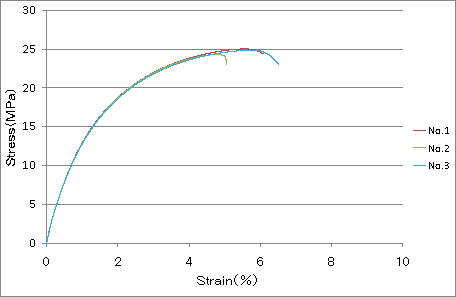
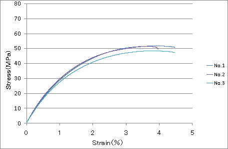
In order to confirm the potential as pressure reduction factors for PE-GF materials for using at temperatures above 20℃ such as the hot drains water of hydraulic generator, we have extra test concerned different temperatures of Stress-Strain curve of tensile strength test between 20℃ to 40℃ as shown in Fig.2 to Fig.7 separate for directions.
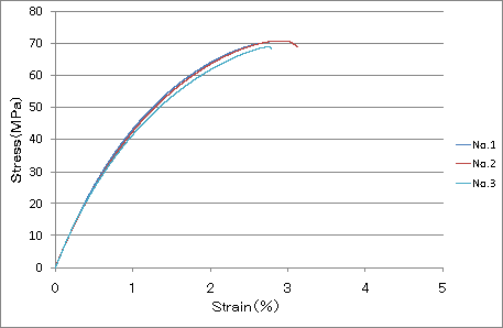 |
| Fig. 2 Circumferential 20℃ |
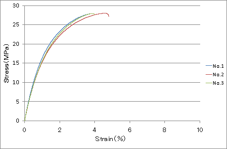 |
| Fig. 5 Longitudinal 20℃ |
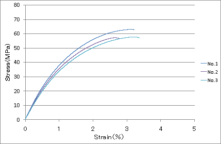 |
| Fig. 3 Circumferential 30℃ |
 |
| Fig. 6 Longitudinal 30℃ |
 |
| Fig. 4 Circumferential 40℃ |
 |
| Fig. 7 Longitudinal 40℃ |
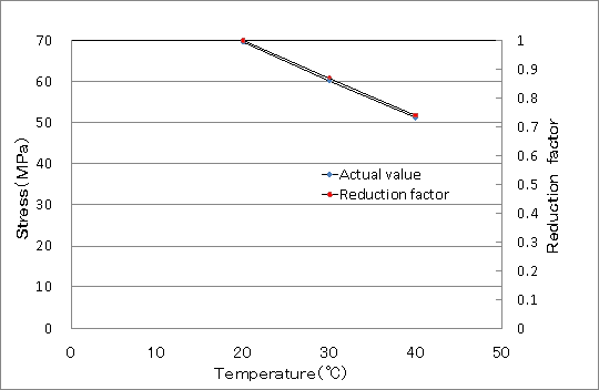
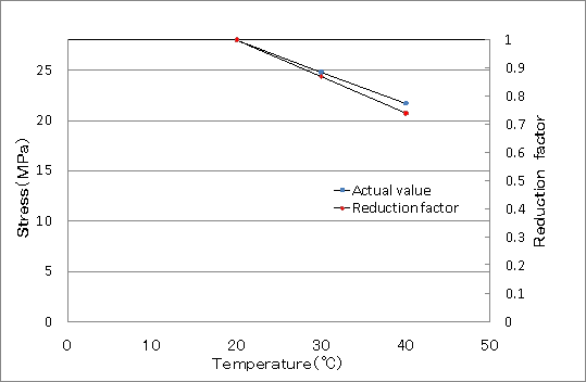
Table 2 represents the comparison with actual tensile strength (average) value of Fig. 2 to Fig. 7 and reduction factors according to ISO 13761.Fig. 8 and Fig. 9 represents the comparison actual reduction ratio and reduction factors. When looking at the results of both, it was simply the same property with polyethylene(PE100).
| Table.2.Comparison with actual value and reduction factors of ISO | ||||
| Direction | Temp | Tensile strength (Actual average) |
Reduction ratio (Actual value) |
Reduction factors (ISO13761) |
| Circumferential | 20 30 40 |
69.6 60.2 51.2 |
1 0.87 0.74 |
1 0.87 0.74 |
| Longitudinal | 20 30 40 |
28.0 24.8 22.9 |
1 0.89 0.82 |
1 0.87 0.74 |
|
Fig. 8 Circumferential |
 |
|
Fig. 9 Longitudinal |
 |
 |
 |
 |
|
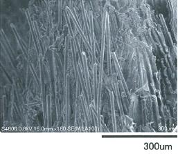
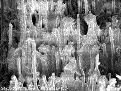
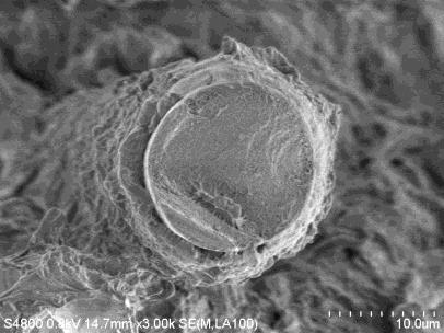
| Fig. 10 Stereoscopic microscope and SEM for circumferential direction | |||
2.Full notch fatigue test (study)
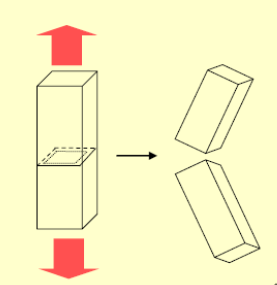 Fig. 11 ISO4437 FNFT
Testing is performed according to standard JIS K 6774 (ISO4437) shown in Fig.11 .Each specimen was notched perpendicular to the parallel length in the middle of the test specimen. The fatigue tests were performed on PE100 and PE-GF characters at 40℃,60℃, and 80℃.
When looking at the results, their curves are approximately parallel both directions. Circumferential stress of PE-GF is more than twice as much that of PE100, although longitudinal stress of PE-GF is as same as that of PE100 shown in Fig.12 and Fig.13.
 |
| Fig. 12 Circumferential |
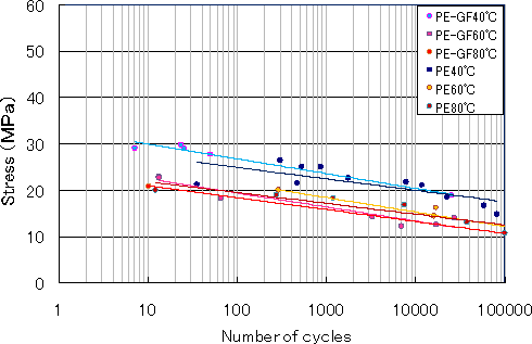 |
| Fig. 13 Longitudinal |
We are believed that it has been influence of spiral cross wounding method and glass fiber directions from extruder. It was very unique characteristics as never before.
There key advantages of PE-GF are high E-modulus by same glass fiber directions and flexibility for longitudinal not less than PE100 property.
In Fig.14 and Fig.15 are cross sections after tested.
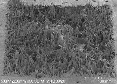 |
| Fig. 14 Circumferential |
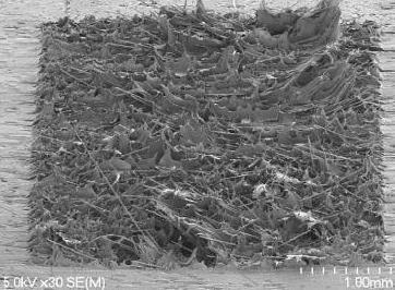 |
| Fig. 15 Longitudinal |
3. Creep test
We study the resistance of creep deflection as the PE-GF pipes to confirm the behavior.
Pipe references:
Water, drainage and sewerage
φ450ID×100mm×14mm
PE100 with GF (PE-GF)
Test condition:
Length: 100mm
Temperature: 23℃
Initial load: 0.34kN/100mm (1%) ,1.01kN/100mm (3%) ,3.37kN/100mm(10%)
The point to be noted is that those pipes does not occur any cracks until pipe deflection exceeds 50% of the diameter shown in Fig.16.
Those can be shown in Fig.17 on a logarithmic scale for 50years.
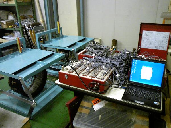 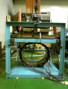 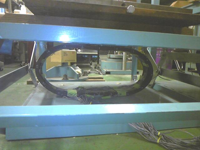 |
| Fig. 16 Creep test |
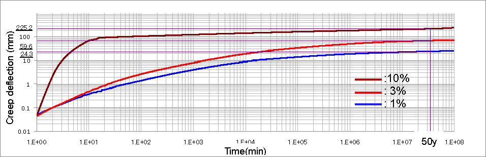
Fig. 17 Creep test
4. Bending test
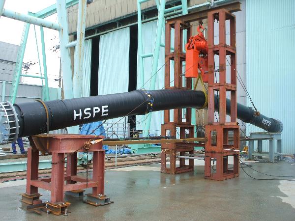 Fig. 18 Bending test
We study the resistance of internal pressure and flexibility as the PE-GF pipes to confirm the behavior as shown in Fig. 18.
Pipe references:
Water, drainage and sewerage
φ450ID×5.5m×14mm with double socket and flange.
PE100 with GF (PE-GF)
Test condition:
Length: 11,300mm
End caps: Flange
Test pressure: 1.0MPa (Internal water pressure)
Joints: Electro Fusion (6 pieces)
Radius of curvature: 95D, 85D, 75D, 65D (D: Inside Diameter)
Strain gauge positions: See Fig. 19.
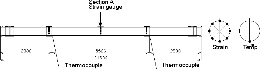
Fig. 19 Position of strain
Our experimental results were indicated as follows.
- There are no leakages at any joints of radius of curvature from 95D to 65D.
- The results are presented in Fig. 20 and Fig. 21, which shows the strain (ε) concerned 2 directions each 8 points around the pipe as shown in Fig. 19.
We have extra advantage for circumferential behavior as shown in Fig. 20.
Theory seems to be similar behavior to actual strain for longitudinal direction as shown in Fig. 21. - PE-GF has to be combined high modulus and flexibility as shown in Fig. 22 and Fig. 23.
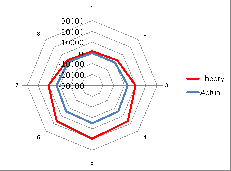 |
| Fig. 20 Circumferential strain (75D) |
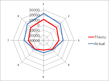 |
| Fig. 21 Longitudinal strain (75D) |
 |
| Fig. 22 Advantage for circumferential |
 |
| Fig. 23 Advantage for longitudinal |
Conclusion
This study shows that the spiral cross winding method can be circumferential orientation of glass fiber. With this way, the quite unique performance of it has highly hoop stress as like GRP nevertheless flexibility for longitudinal direction as like polyethylene. This is in ideal performance with both combination into new pipes. This mean one can conclude that it has quite unique balance of properties between high modulus for circumferential and flexibility for longitudinal.
References
- ASTM F 2720 standard specification for Glass Fiber Reinforced Polyethylene (PE-GF) Spiral Wound Large Diameter Pipe
- DINSPEC19674-1 Plastics piping systems made from glass fibre reinforced polyethylene (PE-GF) for Water supply and for drainage and sewerage under pressure-Part 1:General
- DINSPEC19674-2 Plastics piping systems made from glass fibre reinforced polyethylene (PE-GF) for Water supply and for drainage and sewerage under pressure-Part 2:Pipes
- Report No 9391 Testing of glass fibre reinforced PE-GF 400 pipes produced by KRAH AG(D) with PE XS10B compound (TOTAL PETROCHEMICALS(B))BECETEL
