Design of electrofusion joints for PE100 pressure pipes
Krah America Latina SA has faced the challenge of developing PE100 pressure pipes up to 10kg/cm2. Considering that the resulting stresses are proportional to the pressure load, we started by carrying out a finite element study on a DN800 NP8 pipe
Method: The socket - spigot joint corresponds to a pipe with nominal diameter DN= 800 mm and 43 mm thickness, subjected to an internal pressure of 8 Kg/cm2. The material of the union of the socket - spigot and the pipe is Polyethylene PE 100, Modulus of elasticity E = 2500 Kg/cm2 (long term), Poisson coefficient: 0.45.
The study was carried out for the union by electrofusion, in three different positions of heating element, being the gap between the heating element and the bottom of the socket: case 1 40mm, case 2 60mm and case 3 20mm.
In order to carry out the study of stresses and deformations using finite elements, and given the revolution symmetry of the pipe, a model of π/2 of the pipe was made. A type of solid tetrahedral structural element was used. This element has quadratic displacement behavior and is suitable for models with irregular meshing. Each element is defined by ten nodes having three degrees of freedom for each node: translations in the nodal directions x, y, and z. The element also has capacities for large deformations, plasticity and creep phenomena.
The mesh has been made with an element size of 3 mm, resulting in a number of 58,820 elements and 89,327 nodes.
Results: The stresses in annular, radial and longitudinal directions were determined for the three cases, resulting in all the cases the annular direction the most important one. Consequently, their values are reported below.
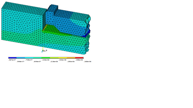
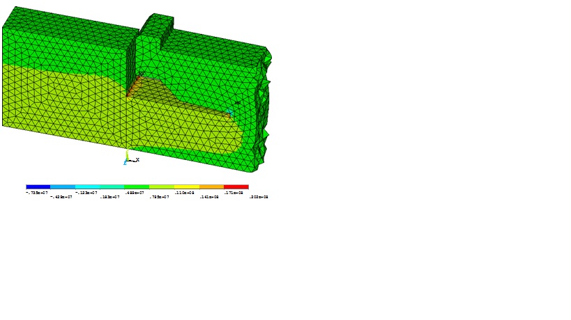
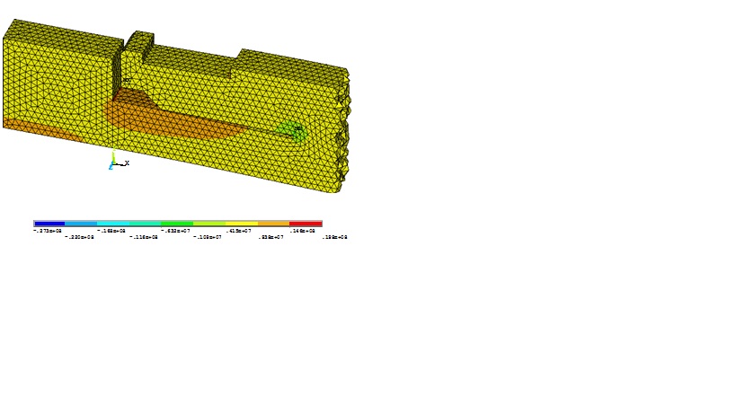
CASE 1 CASE 2 CASE 3
Analysis of results
For the analysis of results, the stress in the ring direction was taken into account. For this purpose, elements of the spigot have been selected in three positions: in the inner radius, middle radius and outer radius of the spigot, for the three cases analyzed. These are summarized in the following table:
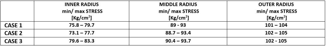
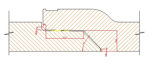
As a conclusion, configuration 2 was chosen for our pipe union design DN800 NP8 and a splicing radius between pipe and spigot was placed according to the following scheme in order to reduce the stress concentration in the spigot/ pipe interface. The exceeding socket length was cut out in order to reduce the couple in the longitudinal plane (see deformation in case 2 diagram)
This couple occurs due to the lack of pressure applied to the surface of the spigot exposed to the atmosphere (as a counterpart of the other end of the spigot that has the water pressure applied to both inner and outer surface) and tends bend the spigot in the longitudinal plane and “flange” out the socket resulting in a more complex stress state.
Taking into account the linearity between stresses and loads and considering the geometric similarity of the stresses, we are able to extrapolate the results in order to design pipe joints of other diameters subjected to different internal pressures. This process was carried out for the design of the rest of our socket - spigot joints for pressure pipes up to DN1500 NP10.
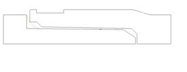
Illustrative example of the resulting profile of the re-designed joints (DN1500 NP10)
We believe that the results obtained are useful in order to better understand the nature of the state of stress present in these sets of complex geometry and which are the possible zones of structural failure.
We consider it is a starting point for further studies that we are carrying out in which it would be interesting to include thermal and dynamic effects. With these concepts in mind, our socket - spigot assemblies for pressure pipes have been redesigned. The resulting geometries are detailed below and operation tests have been carried out with satisfactory results.
Eng. Gabriel Hordij
Eng. Guillermo Heyaca Varela
Krah America Latina SA
Argentina
