Hydraulic calculation of PE pressure pipes
Krah pipes are often used for pressure applications, whether the requested pipe material is a standard High Density Polyethylene (HDPE) or Polyethylene reinforced with glass fibres (PE-GF). For the flow-characteristic and pressure loss the surface quality is essential, since the surface-roughness affects the friction between fluid and pipe wall. Polyethylene pipes (HDPE and PE-GF) provide in general very low roughness values in comparison to steel or concrete pipes. The low roughness and the kind of waxy surface can also avoid incrustations which is another point to reduce the pressure-loss.
Furthermore also the jointing procedure can be important. Any interruption of the surface generates additional turbulences, which increase the pressure loss. In the pipe design that aspect should be considered. A smooth surface after jointing is very preferable, e.g. by using Electrofusion socket / spigot joints.
Especially in comparison with other pipe materials like concrete or steel the advantages of Polyethylene pipes become clear after calculation. By using Polyethylene pipes very often the necessary pipe diameter can be reduced because of better flow-behaviour and less pressure loss!
1. Pressure loss
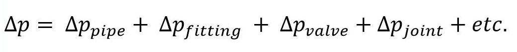
The pressure loss in pipe systems is the sum of all pressure losses for any element of the pipe system. All fittings, valves and constructions have an individual pressure loss and even the pipe joint can affect the pressure loss.
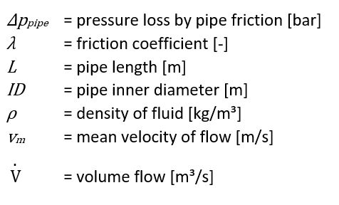
1.1 Pressure loss of straight pipelines
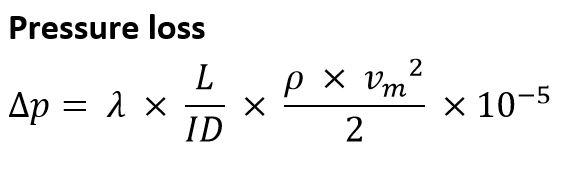
The pressure loss for pressure pipes can be calculated by using the following Darcy-Weisbach-equation, first time established by Jean François d’Aubuisson de Voisin in the year of 1834.
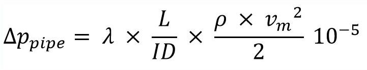
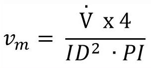
The mean velocity depends on the requested volume-flow and the selected diameter. Usually most pressure pipes are designed with a velocity between ca. 2-3 m/s, to reduce the pressure loss. The velocity effects the pressure loss a lot, because the velocity is considered squared!
Determination of Friction coefficient
For calculation of the friction coefficient, firstly the Reynolds number has to be calculated. The Reynolds number defines the kind of flow. We differ in general between laminar and turbulent flow. The critical Reynolds number is 2320, below 2320 the flow is considered as not turbulent! Also the hydraulic flow characteristic of the pipe’s inner surface has to be considered. We differ between ideal hydraulic smooth and hydraulic rough, in-between a transition area is defined.
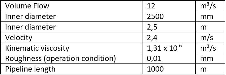
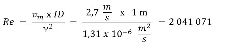
Reynolds number
For calculation of the Reynolds number the following formula can be used:
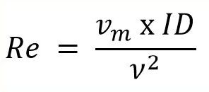
Re = Reynolds number
v = kinematic viscosity of fluid [m²/s]
The kinematic viscosity of fluid is specific and changes under temperature.
For pure water the following values are measured.

Laminar Flow
For laminar flows the friction coefficient can be calculated easily by using the following equation:
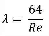
Unfortunately this is not applicable for typical water and sewage application since the laminar flow happens only at very low and unrealistic velocities.
Turbulent Flow
Turbulent flow is the normal situation for pressure pipes. The pipe roughness and the Reynolds number are decisive as to what formula has to be used for calculation. It has to be considered that the flow is never fully turbulent, because at the pipe inner surface only a very thin laminar layer exists. The higher the velocity, the thinner is the laminar layer.
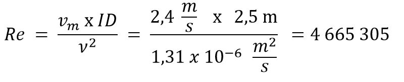
For the pipe roughness (k) it makes no sense to work with measured values at virgin pipes, better is to consider roughness at operation condition. For Polyethylene k = 0,01 mm can be used for calculation. In literature you find for thermoplastic pipes even values of k = 0,007 mm (DVS 2210-1).
Generally, we differ between 3 cases with different physical background:
Case 1:
The pipe wall is ideally hydraulically smooth, the roughness kb = 0 mm.
The inner pipe surface is completely covered by a thin laminar flow layer, before the flow becomes turbulent.
Then following equation has to be used:
But because pipes normally have a specific roughness and are not ideally hydraulically smooth the equation above is not applicable for typically pipe application.
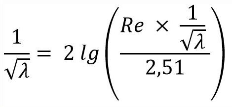
Case 2:
The pipe wall provides a specific roughness and a thin laminar flow layer partially covers the roughness.
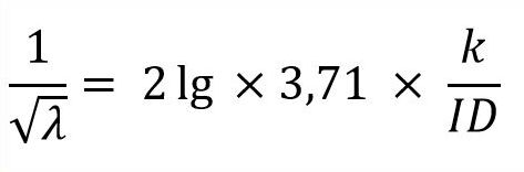
This case is called “transition area” and the following equation has to be used:
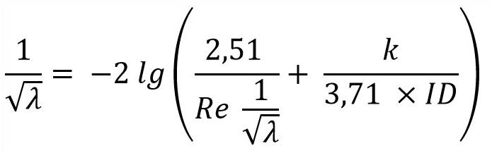
Case 3:
The pipe wall provides a specific roughness and the thin laminar flow layer does not cover the roughness.
Then following equation has to be used:
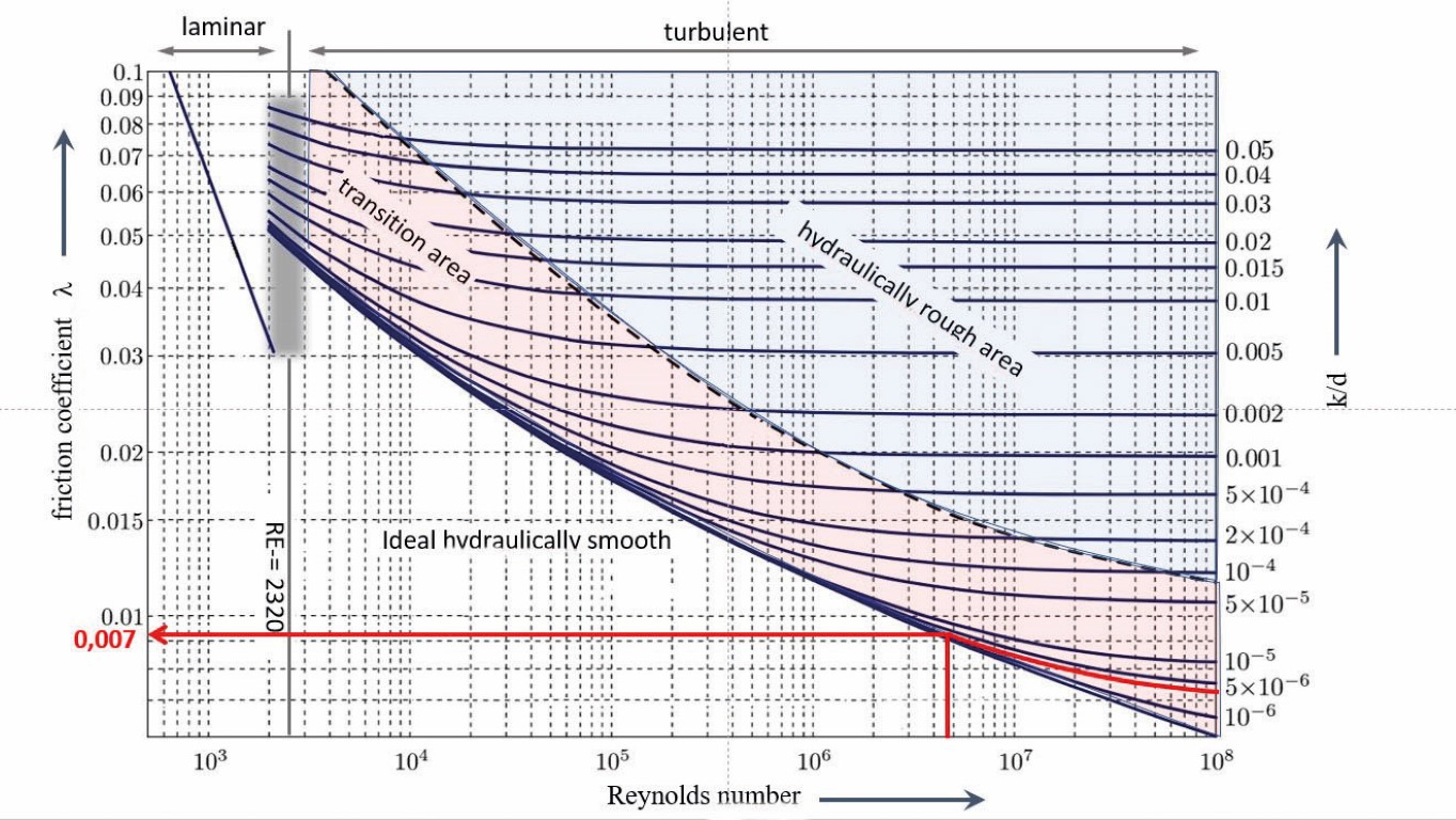
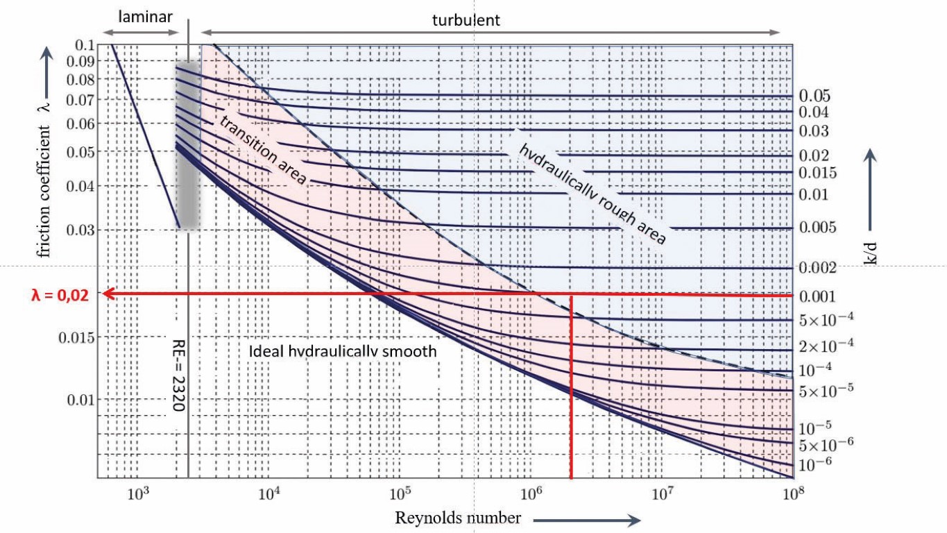
Because the handling of the above-mentioned formula is very complex, software solutions or graphical solutions are usually used. An alternative way is a graphical solution by using the Moody diagram, where all different flow- and pipe- characteristics are considered and the friction coefficient can be determined easily.
Moody diagram:
To explain the handling of the Moody diagram at the end of the report two different examples are drawn into the diagram and parallelly calculated by using the relevant equation.
Further the pressure loss is calculated.
Example A
Intersection of both lines Re and kb/ID is in transition area.
Solution for lamda by Moody diagram and software => λ = 0,007063
Example B:
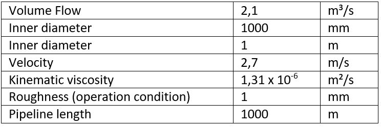
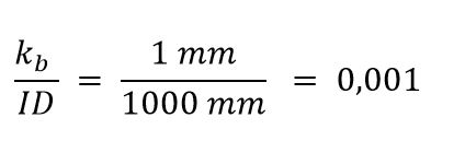
Intersection of both lines Re and kb/ID is in hydraulic rough area.
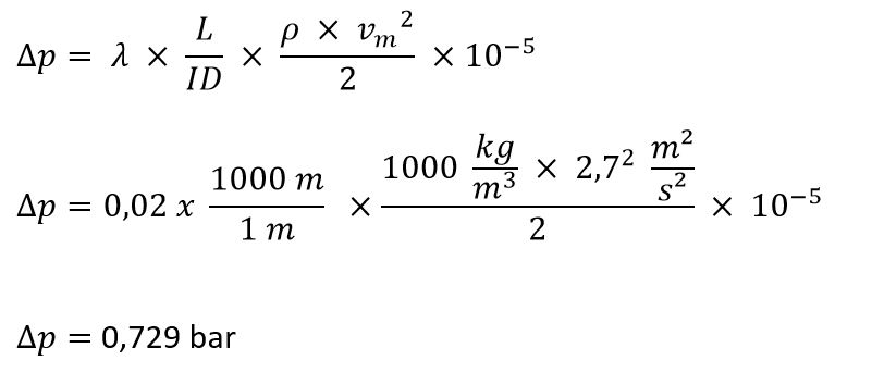
Solution for lamda by Moody diagram and software => λ = 0,01963 ≈ 0,02
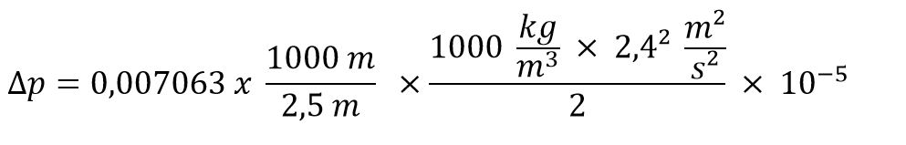
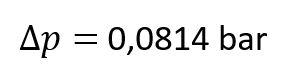
Pressure loss
Pressure loss of fitting
The pressure loss of fittings is another important point, that can be calculated if all fitting are known. Each fitting has a specific and individual resistance coefficient and pressure loss.
The resistance coefficient depends mainly on shape and figure of the fitting and the flow direction. In the literature values for different fittings are described.
For thermoplastic fittings the DVS code 2210 is recommended using.
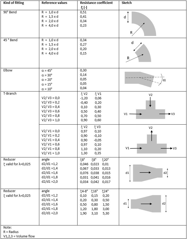
The following equation is valid for fittings:
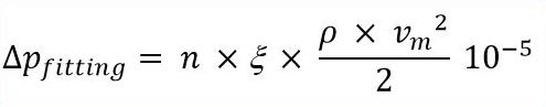
n = number of fitting
Conclusion:
Polyethylene pipes provides very low roughness values and this effects the flow resistance and pressure loss significantly. Further incrustations can be reduced.
Less pressure loss means either the pipe diameter can be reduced or the necessary energy to convey the required volume flow gets reduced!
These are important arguments for both designer and operator.
Author:
Stephan Füllgrabe
Plaspitec GmbH, Germany
