Welded PE Sewage Pipe up to DN/ID3500 for Culvert Construction in Stuttgart Underground Station
As part of the century project “Stuttgart 21” extensive infrastructure measures must be carried out in the region of the new underground station of the state capital of Baden-Wurttemberg. This includes the relocation of several large waste water collectors that are “in the way” of the new station. The existing sewers will be laid (culverted) under the future underground station at several points – pipes and components made of PE100 from Frank GmbH will be used for this project. In several locations the existing sewers are placed (culverted) under the future underground station - for this purpose, PE100 pipes and components by FRANK are used.
Overview of the Building Project
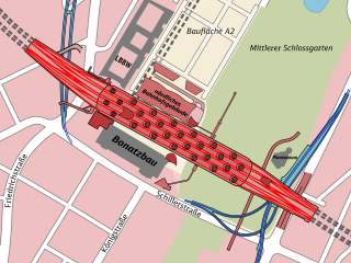
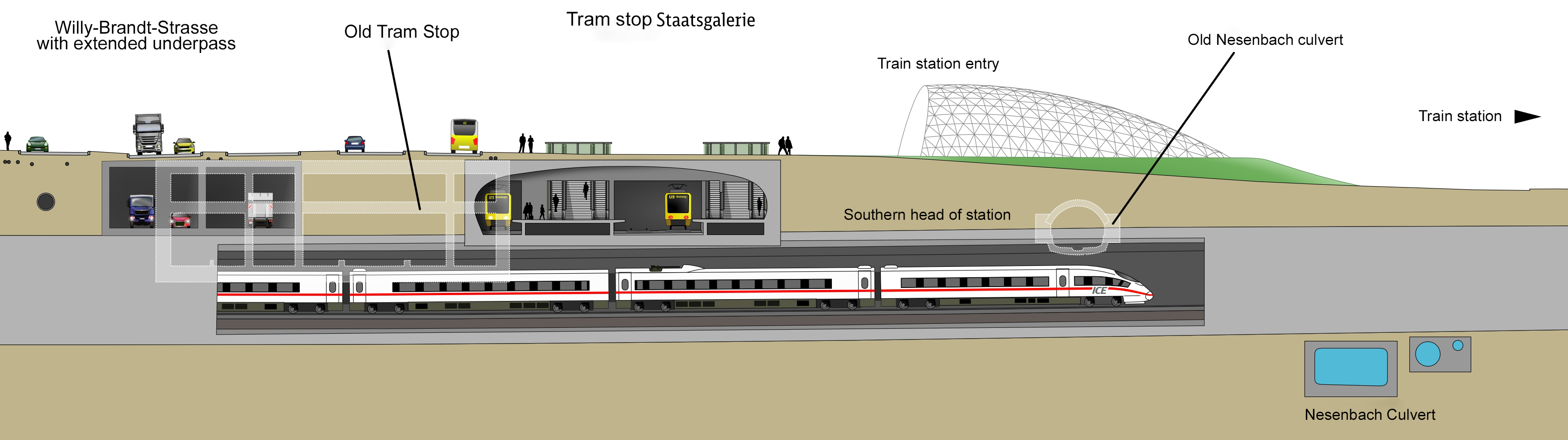
The terminus station, also known as “Bonatz-Bau”, was opened in 1922. Over the past centuries the infrastructure around the station has developed, so that for the new construction of the underground station many existing lines need to be severed and re-laid. Picture 1 shows the location of the underground station compared to the terminus station and the course of the large sewage culverts.
Definition and Operating Principle of a “Culvert"
Wikipedia [2] states that the operating principle of a sewage culvert (see Picture 2) as follows: “A culvert is a pressure pipe to pass under a road, a tunnel, a river or railway tracks etc. The pipe can, for example be a gas, sewage or drinking water pipeline or a groundwater or oil pipeline. In the culvert the liquid overcomes a barrier without pumps having to be used. This is done by using the principle of the communicating pipes, according to which liquids in interconnected pipes always pend to the same level. If now liquid keeps on flowing in on one side, it reaches the same level of height on the other side and can be forwarded almost without any loss of height.” Since the existing collectors (main collector west and Nesenbach) drain in free fall, the fill level in the sewer always corresponds to the current flow rate. In case of low discharge (dry weather - QTW) the filling of the sewer falls back into the dry weather channel. Here, a relatively high flow velocity is generated with a reduced cross-section to prevent deposits. In a culvert, the system of the weather channel no longer works as the culvert would first fill up with water completely before a drain is possible on the other side at the lower gates. This would lead to an extremely slow flow speed, a high dwell time and to depositions within the culvert line. Thus, the side streams are separated in the upper gates – namely in QTW – here, the culvert is always filled as well as in Qkrit and Qmax. Qkrit and Qmax are only flooded when the respective maximum drains are reached. In case of heavy rain all three cross sections of the culvert line are filled. In the lower gates the side streams are led back together again – the further sewage transport is carried out as gravity line.
Introduction of the Subprojects – Material Selection
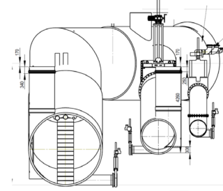
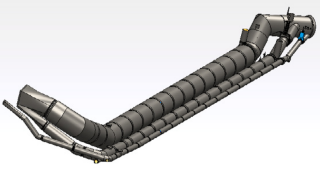
Main Collector West (Picture 3)
The existing cross section of the collector around the “Kurt-Georg-Kiesinger-Platz” is a circular tubbing channel DN3700 with dry weather channel (Qmax ~ 65000 l/s), that was made in closed construction. In the upper gates of the culvert the separation of the side streams is carried out in
- QTW ca. 400 l/s -> culvert DN800 PE100 pipe -> always in operation,always filled-
- Qkrit ca. 3600 l/s -> culvert DN1600 PE100 pipe -> emptied
- Qmax ca. 47000 l/s -> culvert DN3500 PE100 pipe -> emptied
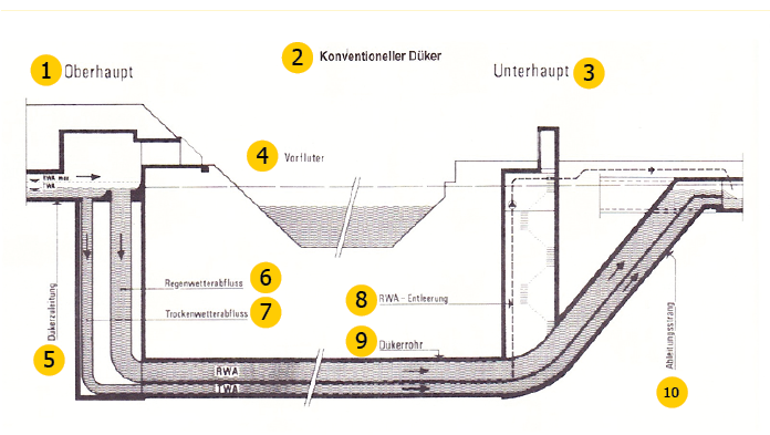
1= Upper gates
2= Conventional culvert
3= Lower head
4= Receiving water
5= Culvert pipeline
6= Rain weather drainage
7= Dry weather drainage
8= RWA discharge
9= Culvert pipe
10= Drainage line
Culvert Nesenbach (Picture 4)
Here, the existing cross section is a typical tunnel vault with dry weather channel – in the upper gates of the culvert a separation of the side streams happens as follows:
-QTW ca. 1500 l/s -> culvert DN1000 – PE100 pipe
-Qkrit ca. 10000 l/s -> culvert DN2400 – PE100 pipe
-Qmax ca. 100m³ /s -> culvert rectangular duct 7,00 m x 3,60 m -cast-in-place concrete
According to Wikipedia [4] “The Nesenbach is a tributary stream of the Neckar with a length of around 13 km. The Nesenbach has “cut through” the basin in which Baden-Wurttemberg’s capital Stuttgart has developed. The small stream used to cross the city from southwest to northeast but has now been replaced along its entire length by the main collector of the same name in Stuttgart’s combined sewer system. [...] As the Nesenbach became more and more polluted over time, it was increasingly vaulted and completely dug in. Today it is the most important main collector in Stuttgart’s sewage system and serves as a sewage and rainwater canal for the entire southern part of the city. It no longer flows into the Neckar near Berg but is fed into the Mühlhausen sewage treatment plant. […]”
Material selection
The original planning provided for reinforced concrete pipes with PE liners as pipe material, the culvert “Cannstatter Straße” was then the first culvert structure at the new station with a nominal width of DN/ID2000 to be designed in this way. During the implementation planning it was determined that the handling of reinforced concrete pipes >DN/ID2000 is not possible in the wide, deep excavation trenches. Furthermore, a solution ..for the large pipe fittings up to DN/ID3500 was needed.
The advantages of the lightweight, flexible pipe material PE100 and the availability of wound sewer pipes made of PE100 up to a nominal width of DN/ID3500 then led to the redesign of the subprojects culvert Nesenbach and main collector West.
Pipe Materials and Pipe Production
The production of the wound PE100 sewage pipes DN/ID800 – DN/ID3500 with integrated E-fusion socket (up to DN/ID2400) as well as manholes and components took place at the Frank Kunststofftechnik GmbH in Wölfersheim. As pipe material PE100 Borsafe HE3490-LS was used. Here are some selected material characteristics:
Density: 940 kg/m³ acc. to ISO 1183
Poisson’s ratio: 0,38
Short-time E modulus: 1203 N/mm²
Long-time E-modulus: 193 N/mm²
Short-time tensile strength: 29,90 N/mm²
Long-time tensile strength: 18,90 N/mm²
Polyethylene (PE100) is a thermoplastic which has, next to a low, specific weight, an extraordinary workability, weldability and flexibility. PE is especially resistant against aggressive media (acids and lies). Furthermore, the molecular construction of the material, which is made of carbon hydrogen, enables a material recycling.
Polyethylene can be recycled up to 100%. In DIN 8074 “Polyethylene (PE) – Pipes PE80, PE100 – Dimensions” and DIN 8075 “Polyethylene (PE) pipes – PE80, PE100 – General quality requirements, testing” the following statement regarding long-term strength has been made: “The operating time previously estimated at 50 years can be extended to at least 100 years due to many years of testing and experience for PE pipes at application temperatures of 20°.”
Production of Spiral Wound Pipes
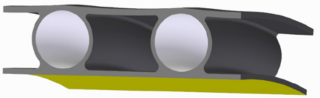
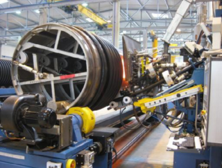
In a molten state, the moulding compound is spirally wound onto a metal mandrel in form of a continuous overlapping strip (Picture 5). A second, functional and/or inspection-friendly inner layer can be applied via a co-extruder. A metal mandrel, which determines the inside diameter of the pipe, serves as calibration. The pipes are slowly cooled by a blower. In this way, residual stresses caused by volume shrinkage and the production process can be reduced. Different wall thicknesses and profile geometries can be achieved by winding the moulding compound in several layers and varying the amount of material applied (Picture 6). PKS® sewer pipes are available in the nominal sizes DN 300 to DN 3500. The basic wall thickness is determined in accordance with the minimum requirements of DIN EN 13476-3 or operational requirements. Production and quality assurance are carried out within the framework of the general building approval Z-40.26-359.
Welding Connections
In the PKS® pipe system (profiled sewer pipe system) the single pipes, manholes and accessories are welded according to the standard with an integrated heating socket (E-fusion), this connection technology is available up to DN/ID 2400. During production socket and spigot are attached to the pipe. When the installation is carried out on site, the spigot is put into the socket and welded together (Picture 7).
The welding parameters are transferred to the welding device using a barcode. The welding device automatically records the welding process.
Static Calculation of the Pipes
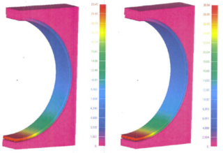
Generally, the static calculation of buried sewer pipes is carried out in accordance with ATV-DWA A 127. For the preselection of a suitable pipe, this calculation method was also used. Much more precise and illustrating the installation conditions better is a calculation using Finite Elements (FE). With this method the installation conditions and the pipes are divided into small elements (finite elements). This results in a very precise calculation. As the culvert pipes were completely encased in concrete, the groundwater level and inner pressure values were decisive for the calculation. For flexible pipe materials three checks always have to be performed - deformation, stability and stress check (Picture 8). An essential condition of the contracting authorities was that the evidence of a service life of 100 years could be given.
Details Main Collector West
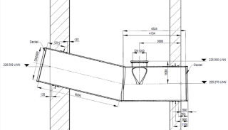
After the basic decision for the pipe material PE100 and the static calculation had been made, the work planning of the culvert sections was carried out in 3D. The individual parts for the production drawings were taken from the overview design (Picture 9). First, component 1.1 was installed in the lower head to be able to connect the necessary bypass for the duration of the construction period. Since component 1.1 (Picture 10) could not be assembled in one piece, production in the factory was divided into two parts. After delivery in Stuttgart, the homogeneous joining was carried out by hot gas extrusion welding. An essential aspect in the selection of the pipe material was the weight and thus the possible handling of the pipes and components in the deep and wide excavation pits. The concrete pipes up to DN3500 included in the original planning could only have been moved with a very large mobile crane. However, there was no space available on the narrow inner-city construction site for a corresponding mobile crane. The PE100 pipes could be completely moved and installed using the existing tower crane.
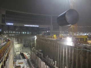
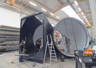
The weight of the individual pipes DN3500 with a length of 5.50 m was approx. 5 tons. As the transports were only allowed to be carried out in times of low traffic volume within the scope of the “traffic law exemption permit”, the pipes were also unloaded and brought into the excavation pit during the night (Picture 11). A further advantage of the pipes and components made of PE100 is the high degree of prefabrication, which made it possible to prepare complex components and pipe fittings in the workshop. For example, DN3500 pipe bends (Picture 12) and access shafts could be prefabricated, delivered and installed.
Stairways (Picture 13), which were necessary to comply with accident prevention regulations, could also be prepared accordingly in the inclined and ascending sections from the head and to the lower head. For the operator of the culvert structures, the “Stuttgarter Stadtentwässerung”, a uniform, bright, inspection-friendly inner layer of the pipes and components was very important. This was made possible by the coextrusion process used to manufacture the pipes. The transitions from rectangle to round (Picture 14) in the head could be realized with unwinding made of PE sheet material.
Details Culvert Nesenbach
For the Nesenbach culvert, the main cross-section (Qmax) must be designed as an in-situ concrete rectangular channel, as no precast elements could be used for the dimension (7.00 m x 3.60 m). For the two “small” pipes DN2400 (Qkrit) and DN1000 (Qtw) the same construction method was used as for the main collector West. The pipes and components made of PE100 were constructed as far as possible in the same way as the main collector west.
There, the installation in the very deep excavation trench (20 m) was also carried out with a tower crane. The individual pipes DN1000 and DN2400 were welded using the integrated electrofusion socket. The tightness test was then carried out directly with a socket testing device (Picture 15).
The method “L” from DIN EN 1610 “Testing of individual joints” was used. This ensured that only “tight” pipe connections were encased in concrete. The lowest point of the Nesenbach culvert is the pump house. As with the main collector west, the pipe cross-sections Qkrit and Qmax are emptied after filling (after a rain event) to prevent rotting and odour.
To be able to construct the underground building in advance, “insert parts” (Picture 16) had to be delivered long before the actual pipe sections to be set in concrete. The pipe sections “Crossing” and “Climbing” were then connected to these inserts after the construction of the excavation pits. Conclusion(August 2018) - main collector West in operation - culvert Nesenbach under construction) - Feasibility produced by PE100 as pipe material- High degree of prefabrication- Easy handling with tower crane due to low weight- Permanently tight due to welded joints - Adjustment work on site possible- Flexible material compensates for settlement differences - Guaranteed long service life – design period --> 100 years
Literature / Sources
[1] https://www.bahnprojekt-stuttgart-ulm.de/aktuell/
[2]https://de.wikipedia.org/wiki/D%C3%BCker
[3] https://link.springer.com
[4]https://de.wikipedia.org/wiki/Nesenbach
[5] https://www.bahnprojekt-stuttgart-ulm.de | Foto: Achim Birnbaum, Stuttgart
Autor: Jochen Obermayer, FRANK GmbH, Mörfelden-Walldorf / Germany
