Change in length by changing operation conditions
A change in length of plastic pipes are caused by changing operation conditions. We differ between change in length by change of temperature, chemical influence or pressure load. Generally, we differ in two design solutions for handling an occurring change in length:
- The pipe is hindered for change in length due to fix points or due to restrained installation conditions (e.g. buried pipes).
- The pipe can move in axial direction and resulting elongation or contraction is compensated by compensators or by bending.
No matter how the change in length is handled, it can be calculated easily and has to be considered for the design of the plastic pipe system. The necessary information and the equations for the calculation are mentioned hereinafter.
Temperature influence
If the plastic pipe is exposed to different temperatures of medium or ambiance, the pipe is disposed to change the length. The change in length can be calculated as follows:
![]()
∆LT = Change in length due to temperature change [mm]
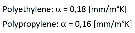
α = Linear expansion coefficient [mm/m°K]
L = Length of considered pipe string [mm]
∆T = Maximum difference in pipe wall temperature [°K]
The linear expansion coefficient differs in considered temperature and material, but following average values can be used for design:
Chemical influence
Polyethylene and Polypropylene generally provide a very good resistance against a multitude of chemicals. The resistance is very good documented in the literature, but at some chemicals it may come to a change of length by swelling. Chemicals like solvents could diffuse into the pipe wall and initiate a swelling effect. It has to be considered, that also the mechanical strength decreases. The expectable change in length can be approximately calculated by using a swelling-factor. A typical swelling-factor fCH for Polyethylene and Polypropylene can be assumed between 0,025 and 0,040.
![]()
∆LCh = Change in length due to chemical influence [mm]fCh = Swelling factor [-]L = Length of considered pipe string [mm]
Pressure load influence
Internal pressure results in length expansion of a closed and frictionless installed pipe-system. The theoretical expansion can be calculated as follows: For solid wall pipes and profiled pipes with closed inner wall and no outer wall (PR,OPR):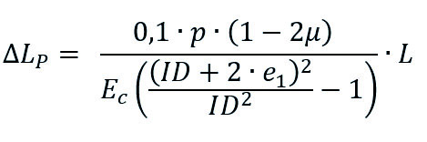
For profiled pipes with closed inner and outer wall (CPR):
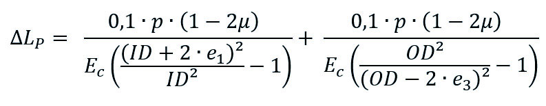
∆LP = Change in length due to inner pressure [mm]
μ = Poisson’s ratio
p = operation pressure [bar]
L = Length of considered pipe string [mm]
Ec = Creep modulus for considered temperature and time [N/mm²]
OD = Outer diameter [mm]
ID = Inner diameter [mm]
e1 = Inner wall thickness [mm]
e3 = Outer wall thickness [mm] For calculation of the total change in length all aspects must be considered:
![]()
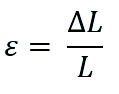
The change length related to original length is accordingly:
If the change in length is hindered by e.g. fix points, axial stress is occurring. That has to be considered in the load scenarios as well as the stress is decreasing by time because of the creep behaviour of thermoplastics.
![]()
Fax = Axial forces due to hindered change in length
Aax = Axial area (projected area in axial direction) [mm²]
Buried pipes
For buried pipes the friction between the outer pipe surface and the surrounding soil is sufficient to avoid change in length. If Krah pipes with outer profiles are used, the pipe gets more or less anchored in surrounding soil. The axial forces are carried by the soil embedment. Thrust blocks, as well known from the installation of rigid pipes (e.g. concrete or steel), are not needed for Krah pipes if all elements of the pipe-system are homogenously jointed by Krah Electrofusion or other standardized welding process.
Above ground installation
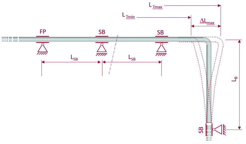
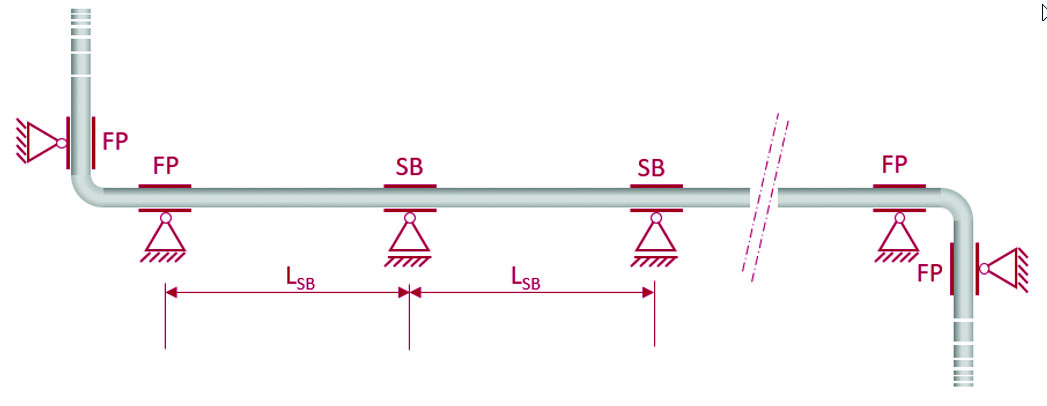
For pipes installed above ground, the change in length is normally compensated by compensators or by bending (Drawing 1). If compensators are used, the needed axial force to ensure adequate function of the compensator should be verified. Directed bending can also be used to compensate change in length. Existing or also artificial bends of 90° can be used for it. In this case, it is important to place fix points (FP) in the pipe system to ensure that the elongation and contraction will happen in a controlled way. More details for calculation and design of minimum bending length LB you find in the relevant standards e.g. DVS 2210. The pipeline can also be installed with blocked change in length by using fix points (FP) at both ends of each straight pipeline section (Drawing 2). The axial forces must be transmitted accordingly through the anchorage elements. Between the fix points, sliding bearings (SB) must be placed to avoid laterally deflection. The frequency of sliding bearings depends on expected compression stress.The maximum distance between sliding bearings can be calculated as follows:
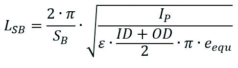
LSB = Maximum distance axial forces due to hindered change in length [mm]
SB = Axial buckling safety factor [-]
IP = Moment of inertia of the pipe [mm4]
eequ = Equivalent wall thickness [mm]
For correct determination of bearing distance also the deflection by dead weight and live load has to be considered:
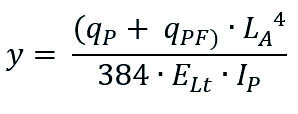
y = theoretical deflection of pipe [mm]
qP = distributed load by pipe weight [N/mm]
qPF = distributed load by pipe filling [N/mm]
ELt = flexural modulus longterm [N/mm]
The recommended maximum deflection is 1/750 of the bearing distance. Please consider, especially for solid wall pipes, that such calculations presume that the pipe provides sufficient stiffness and is not deformed by the loads. Profiled pipes have a lower dead-weight and provide mostly already by nature the required stiffness to avoid deformations.
Author: Dipl.- Ing. Stephan Füllgrabe, Krah Pipes GmbH & Co. KG
 Click here to order your coffee