Relining with large diameter Polyethylene Pipes
Damaged and leaky pipes out of concrete, GRP, steel, ductile iron can be relined and renovated with Profiled Polyethylene Pipes in almost every diameter. Here, the old pipe serves as an empty conduit for the new pipe out of PE and therefore a completely new, self-contained pipe system can be built.
However, the use of profiled pipes especially in big diameters creates new stable pipe systems with a high static load capacity. For the static calculation of the new pipeline two things must be taken into consideration, the installation process and the operating condition of the pipeline. The new system will benefit from the extremely long service life of polyethylene pipes (> 100 years).
|
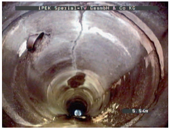
old and damaged sewer |
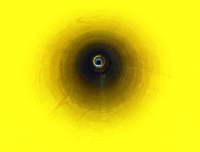
new relined sewer |
The relining process with polyethylene pipes has proven its reliability in almost all fields of application for many years:
- Renovation of leaky sewer pipelines
- Renovation of corroded drinking water pipelines
- Provide a seal against leakage or infiltration
- Gas supply systems (Changeover to higher operational pressures)
- Renovation of inverted siphons
- Industrial applications (aggressive media, acids, alkalis etc.)
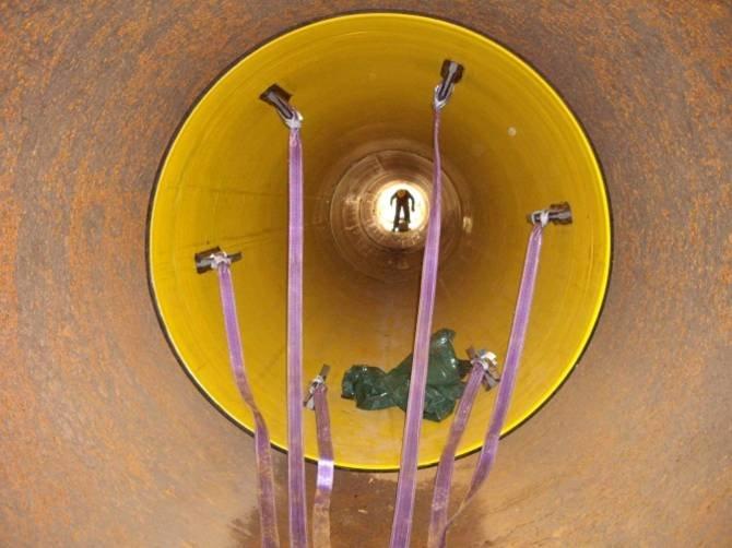
During the relining process with large-diameter polyethylene pipes, the pipe lengths are either inserted or drawn-in according to the application and environmental conditions. Which procedure will be selected depends essentially on the space conditions prevailing on site and of course on the existing machines and tools.
The occurring load for polyethylene pipes is completely different during the pulling through process in comparison to the insertion. This must be considered when dimensioning, during the selection of materials and in the selection of the pipe connection.
Pulling through process
During the pulling through of a pipeline, the pipeline is exposed to axial tensile loading. This leads to an expansion of the pipe. This effect is reinforced by the bending loads which can arise in the angles of the old pipeline.
The insertion forces are increasingly dependent on the length of the pipe to be installed, the weight of the pipeline, the ring gap, the interior surface of the old pipe or rather the friction between the old and the new pipe. The old pipe must be cleaned and if possible removed from encrustations. It is also advisable to apply enough lubricant in order to reduce the friction. Water is also often used for this reason.
Separate sliders which are fixed on the outside of the new PE pipe or in the old pipe. The choice of the correct product for the reduction of the frictional resistance always depends on the corrosion status and the cleaning condition. The choice of the pipe connection can have an impact on the arising friction forces; this is particularly the case if the connection sockets can reduce the ring gap.
 The external pipe surface is mechanically stressed during the pulling through process. Notches and grooves can occur and must be considered when making the static analysis. Notches and grooves can be a weak spot regarding the durability of a new pipe system. The PE raw materials were continuously optimized in the last years especially for this kind of load. Advanced polyethylene pipe materials of strength grade MRS 8 or MRS 10 have therefore a greater groove insensitiveness and resistance to slow crack growth. The pipe producers are indicating special values of many kinds in their data sheets according to several testing methods (Notch-Test, 2-NCT, FNCT etc.). These should give information or at least a reference point regarding the resistance against slow crack growth. Depending on the respective country and the application there are some national defined minimum values. The used materials must meet the requirements. The German Institute for Building Technology (DIBt) sets the following minimum values for test stands for wound pipes out of PE100 for industrial application with regard to
FNCT (Full Notch Creep Test) according to ISO 13770 e.g. : 300 h bei 4 MPa, 80°C, Akropal N 100.
The maximum permissible load during the pulling through process depends on the selected pipe wall cross-section and on the selected welding method. The force application of the pull rope or of the pull rod into the pipe must occur very evenly in order to reduce additional loads. It is recommendable to use a tension-head or tension anchors which need to be distributed at the periphery. A measuring box must be integrated within the pulling system in order to monitor the force application. The measuring box is able to advise the personnel when the tensile load exceeds the permitted degree due to unforeseen obstacles or a to high friction resistance. The pulling through process must be closely monitored and comprehensively documented. Especially angular deflections within the pipe string can lead to a unexpectedly high tensile resistance.
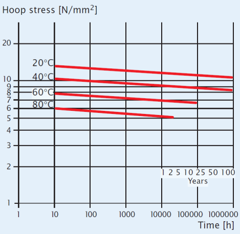
For the calculation of the permissible tensile force, the following factors have to be taken into account – the expected loading duration and the ambient- pipe temperatures. The tensile loading can last a few minutes or several hours depending on the length of the pulled pipe segments. In practice, the load period is often set with 24 hours. The corresponding tensile dimensioning can be taken from the creep strength curves, which are listed in the relevant standards or which are provided by the respective pipe producers.
![]()
Fax = axial forces [N]Aax = axial area [mm2]σ = design strength (from creep rupture curves) [N/mm2] for the required time and temperature
CW = Welding factor [-]Sf = safety factor [-]
The respectively thinnest and weakest wall thickness is the decisive factor for the dimensioning notably in the field of profiled pipes. The same also applies in individual cases within the spigot or the preformed socket. The welding factor can be found in the applicable standards. The Manufacturer’s instructions are binding for the electro fusion connection. The pipe producer can get an overview of the efficiency of the weld connection by taking a tensile specimen of an exemplary weld according to the ISO 527 standard.
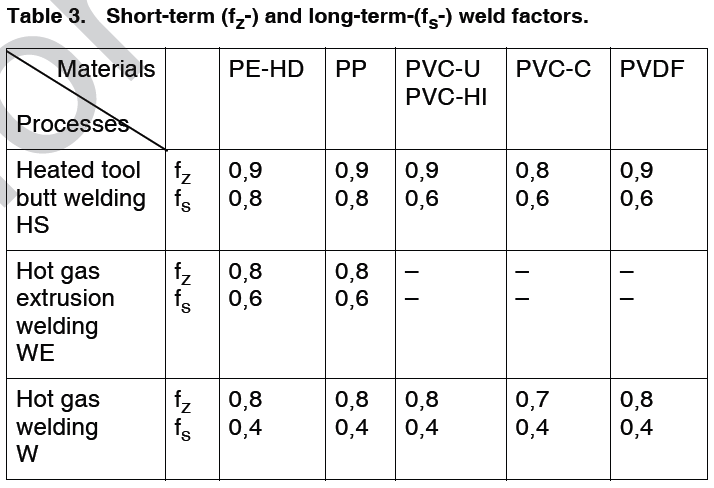 Welding factors according to DVS 2203-1 / 2205-1: Welding factors according to DVS 2203-1 / 2205-1:
|
 Source: Technical Manual-Materials used in Pipe Extrusion, LyondellBasell Source: Technical Manual-Materials used in Pipe Extrusion, LyondellBasell |
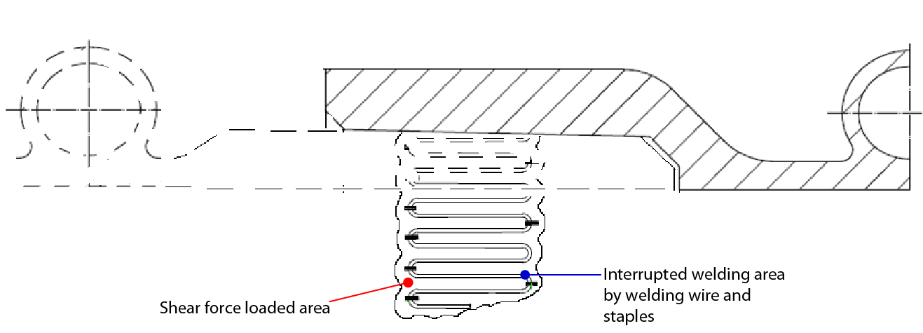
When using electro-fusion sockets, it should be noted that the transferable shearing stress comes to around 50 % of the hoop stress. For the calculation of the subject to shear welding area, the interruption by welding wire must be considered.
![]()
Fax = axial forces [N]Aw = welding area (without wire area) [mm²]σ = design strength [N/mm²] for the required time and temperature
CW = Welding factor [-]Sf = safety factor [-]
Push in procedure
During insertion of the pipe line, the line is not loaded on tension, it is primary loaded on distortion, buckling and compression. The loading duration is similar to the pulling through process and depends on the length of the pipe segments.
For the calculation of the compression stress it is possible to apply to the creep strength curves. The typical values of the pressure resistance are normally higher but however, it is useful to keep the deformation exposed through higher stresses relatively small in order to prevent forming of the shape of the pipe.
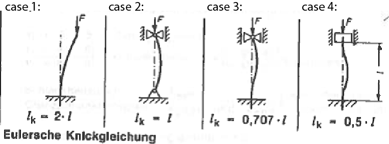
The used formulas for the distortion and buckling are reflecting the ideal circular /cylindrical condition. The stronger the pipe deviates from this, the lower is the resistance against distortion and buckling (Stability Consideration).
Formula for calculation of critical length
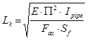
Lk = buckling length [mm]Fax = axial compression forces [N]Ipipe = Moment of Inertia of pipe ! [mm4]E = flexural modulus [N/mm²] for the required time and temperature
Sf = safety factor [-] (should be 2 for stability calculations)
with:
![]()
Ipipe = Moment of Inertia of pipe ! [mm4]OD = outside diameter pipe [mm]eequ = equivalent wall thickness pipe [mm] (at solid wall pipes = wall thickness)
Euler case 4 is equal to situation of Relining-Pipe, therefore is the critical length “Lk” equal “2 x L”
Injection grout mortar
When designing the new pipe for taking the load by soil, traffic etc. the space between the old and new pipe must be filled with injection grout mortar. This procedure is necessary to generate a defined load situation. Static calculations for relining pipes can be done according to ATV M127.
During the injection procedure the pipe is stressed by radial buckling. The buckling pressure depends on the injection pressure and hydrostatic pressure due to the density of the grout mortar and the height between the pipe and grout mortar tank.
The radial buckling resistance of a pipe can be calculated as follows:
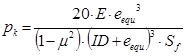
E = flexural modulus [N/mm²] for the required time and temperature
ID = inner diameter pipe [mm]eequ = equivalent wall thickness pipe [mm] (at solid wall pipes = wall thickness)
Sf = safety factor [-] (should be 2 for stability calculations)
Furthermore the lifting force during the injection process must be kept in mind. A distance holder at the crown between the old and the new pipe can reduce the lifting force. In any case, the lifting force must be lower than the weight force of the considered pipe segment between two distance holders. To avoid floating of the new pipe, the pipe can also be filled with water during injection of the grout mortar.
![]()
Flifting = lifting force [N]OD = Outer diameter pipe [mm]Ldh = distance between distance holder [mm] (at solid wall pipes = wall thickness)
γgm = Density grout mortar [kg/dm³]
In summary, there are many load cases to consider for designing a relining-pipe-system. The described technical backround show only a part of it and of course there is more. But at the end all based on physical effects and plastic engineering!
Plaspitec provide Engineering and Consultancy for plastic pipes Systems!
Dipl.-Ing. Stephan Füllgrabe
Managing Director
Plaspitec GmbH, Cologne, Germany
