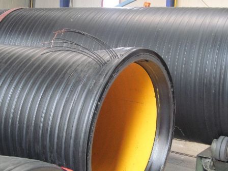
Large diameter structured HDPE pipes in marine projects
Large diameter structured HDPE pipes in marine projects
On the occasion of the recent Krah Community meeting, I have 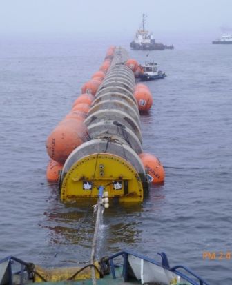
been requested to give a presentation about the installation of
PE Structured Pipes (PESP) in the marine environment.
Instead of staying on the actual subject, I went back in time to
introduce the PESP from their introduction in the early 60s.
After a start with land and marine oil pipelines – my initial “big
inch”, the American term for large pipes, was a 32”, I became
interested in the thermoplastic pipes in the 70s and later in the
thermosetting ones, I could meet several of the major players in
the field of pipes and could experience the developments of the
“market” from the “small pipes” to the present 4 meter pipes,
available now as both in HDPE and PP and in FW GRP as shown
here.
Before going to the subject of marine projects, I would like to go
back to the 60s, when HDPE pipes started to appear in the civil
water and sewer pipeline market.
For simplicity, I will use PEEP for HDPE extruded, solid wall pipes,
and PESP for the HDPE structured pipes, both ribbed or double
wall.
Despite their early appearance, together with extruded pipes,
PESP were not considered for marine projects and their use
remained sporadic until the end of 90s – and is still rare at
present.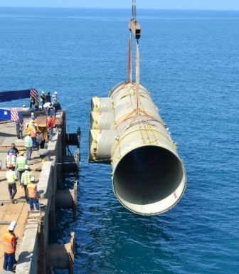
In my opinion, this has been due mostly to the average diameter
of PEES outfall projects, which remained under ND 1600 more or
less until the end of the 80s, only recently reaching ND 2500.
On the other hand, we have seen an explosion in the use of GRP pipes for medium-large diameter
industrial sealines, gaining a large slice of the market. It became, at the end of the century, a
pursuit race, with PEEP growing to ND 2500, GRP to ND 4000 and PESP entering in the match with
its possibility to reach the ID 4000.
Why did structured pipe started to be considered as marine pipes so late?
The delay had little to do with the pipe characteristics; instead, doubts of clients, engineers and
contractors on the suitability of PESP pipes in marine projects were prevailing for a long time,
fueled by the PEEP producers and the presence of an “easy” pipe, GRP.
We could start our tale with “once there was a baby corrugated pipe”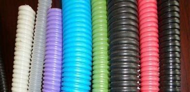
….not those nice colored ones, a black, ugly sewer pipe.
PESP appeared in the civil pipeline market in the 60s, in parallel with
PEEP, in relation with the development of the thermoplastic resins and 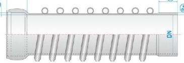
of the production machines.In that period, I was a “steel pipeliner” and only I converted to plastics
in the 70s, looking back to the PEEP and PESP origin out of curiosity.
Back in 1964, PESP pipes were originally produced with thin walls and
welded tubular ribs applied spirally. 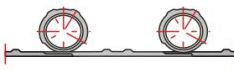
Despite some “incidents” caused by the collapse of the ribs, originally
formed on cardboard rolls, the pipes found their application in the
fields of sewers and large tanks.
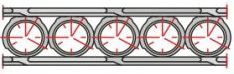
More or less in the same period – the early 60s – Henze also started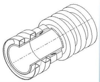
its activity in the spiral formed pipe and tank sector.
The concept of production on mandrel was more or less the same as
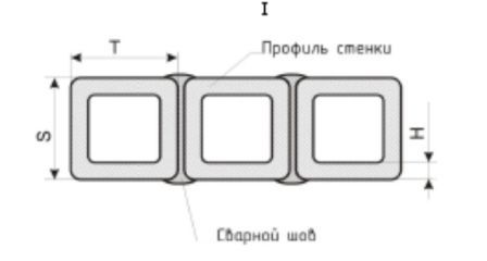
bauku, but the design of the ribs was in favor of “square” instead of
“round” ones.
Despite the evident difference in the connection between
supporting wall and ribs, Henze production, as well as
other similar types, suffered the same fate: not to be
considered suitable for marine projects
After starting my activity in the PE pipe sector in the mid-
70s, both on land and marine projects,
I got only marginally interested in PESP, even though they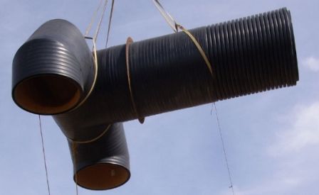
were also produced in Italy, due to a couple of outfall
projects which caused relevant installation headaches
and required a lot of effort and good will from the
contractor to complete the installation.
It was evident that those early pipes with a thin single wall
and applied ribs were not suitable for underwater
installations, due to the low values of axial and bending
strength and the problems with the installation of ballast
blocks.
While mostly working with PEEP - solid wall, extruded pipes - I continued to follow the
developments of the structured pipes, with an eye to their possible use in water and focusing on
2 aspects: the characteristics of the wall, therefore the resistance to the installation stresses, and
the high buoyancy. Frankly speaking, I was not paying real attention to the 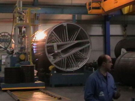
production machines, it was for me all “production on
mandrel”, similar to the production of cross filament
winding GRP …. except that the thermoplastic resins are
fused by heat and the thermosetting ones are hardened.
I was interested instead in the possibility of PESP for large
diameter outfalls and dedicated some time to study their
characteristics in view of their use in sealine projects.
I was in contact with Henze as early as the 80s, and, with
their cooperation, we tried to propose PESP also for marine
installations. However, all trials to propose PESP instead of
PEEP were spoiled by the resistance of the clients to the
change.
In reality, the Clients and engineers were not yet 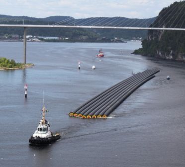
psychologically ready for marine use of PESP.
They were in love with PEEP, which was growing up in
diameter and was attractive due to the possibility to receive
it in long strings by sea.
At the same time the production of GRP on continuous
mandrel was quickly overcoming PEEP in diameter.
The traditional PESP – spiral formed both with ribs or with double wall – was still present, but the
demand for diameters above 1200 was quite low and, moreover, there was the novelty of the
coextruded ribbed pipes for sewer application.
For a long time, the reaction to PESP was …..
An inversion in this tendency started in the last years of the last century and early in 2000,
revaluating the possible use of PESP underwater.
The Client/Engineer/Contractor “braking system” was (and is) still functioning, old habits die
hard… and PEEP and GRP were already produced in many countries.
Around the world, in the last 15-20 years, PESP in HDPE (and PP) have continued to be developed
as single wall/double wall with round ribs, single and double wall with square ribs and double
wall with enclosed round ribs.
In the same period, significant improvements have been made in the field of jointing, passing
from the early bell and spigot with gasket to face-to-face welding, electrofusion welding both
with bell and spigot or double bell, etc.
In the early years of 2000, engineers and contractors became more confident in the possibilities
given by large diameter PESP, however they were still facing the doubts of the clients.
Despite my continuing interest, I do not know when PESP really started to be considered 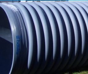
as a “marine pipe” and what I learnt – good and bad - was indirect.In the late 90's,
producers were active in the field with 4 basic “styles”. The best known were bauku and
Krah – with the classic ribbed pipe.
Despite initial problems, bauku has been installed a 3000 PP pipe in the
Wilhelmshaven power plant.
As far as Henze, the company
continued the production of the “square rib” pipe, but despite the
quality and the suitable characteristics, no “marine” result was achieved.
Henze produces both single wall and double wall with square ribs, therefore
a pipe ideally suitable for the sea. Recently, a bad copy of the square rib
pipe has created some ripples in the PESP market … I will mention it later.
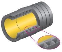
Another type, recently employed with success, was (and is) produced by PPA with the Krah technology inSpain. It can be defined as a massive double wall with internal round ribs.The PPA pipes are probably the best known, due to the recent success of the Peru outfalls.
The fourth product which needs to be mentioned has the brand name “Weholite”, produced by
KWH, (now Uponor).
Its use for marine projects has come to attention due to the use of a special fluid, not-hardening
concrete, to fill the ribs and to obtain the needed negative buoyancy.
A few projects were competed, but, while the idea of using a ribfiller 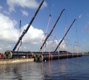
is logical, it is in my opinion impractical.
The point in favor is the theoretical possibility to fill the rib cavity
with grout, in order to obtain part or all the necessary submerged
weight and to avoid the traditional ballast blocks.
However attractive, and whichever heavy material could be
available – also fluid bentonite with density = 3000 kg/m3 was
considered among the possible fillers - the filling of the voids in a 6
m pipe can be a frustratingly long task.
Just as a rough example, a single 6m, ID 3000 pipe could require up to 7-8 m3 of filler and there is
always the doubt that some voids can remain, causing an irregular ballast distribution and point
stresses.
After a lot of brainstorming (and some trials), as far as I know the idea is almost abandoned.
Obvious solution? Do nothing … or drill the ribs to permit the entrance of water.
The filling with water will bring the apparent density of the submerged pipe, if not to the 960
kg/m3 of PEEP, to a “reasonable” value of 850-900 kg/m3 in a short while, since the air will slowly
bubble out from the submerged pipe.
This solves one of the negative aspects of the marine PESP, giving the engineers and contractors
the possibility of calculating the ballast without exceeding the real medium-long term needs and
at the same time to use the excess buoyancy as an “aid” to reduce the submerged weight during
the sinking operations.

But …. If the pipe breaks?
Apart the fact that also PEEP may break, due to
handling errors or unaccounted external forces, in
the case of PESP, as well in cases involving other
types of pipes, the problem can be the pipe structure before the
handling.
Discussing which party is guilty in the case of failure – engineer, producer, contactor,
supervisor - is comparable to the discussion on which came first, egg or
chicken.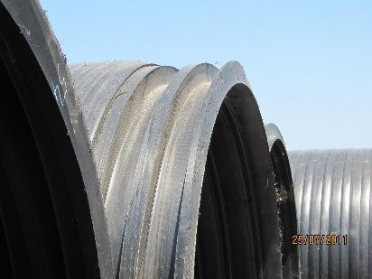
While in the case of PEEP the main chances of damage lay on
installation errors, for the PESP it is more probable that the failure
is a consequence of a defect of fabrication or of a pipe weakness,
due to wrong design.
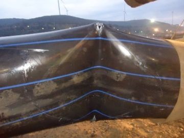
An interesting example has been the recent failure of a PESP ID
2000.
On paper, the pipe seemed “decent”, but looking at it in the field,
both the section and the welding raised several questions on the
possible risks.
The early objections were neglected by the Client and, despite the
evident risks due to the weak profile … … and to the weather,
jumping from 20° under the sun to -5° under the snow, with a
permanently rough sea.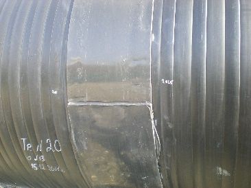

The assumption was that the bond of the square ribs was good and 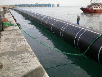
that, with the due precautions, the pipe could be installed on the 20
m deep bottom, despite some “strange” design aspects.
I do not want to enter in the details of the launching way …but
despite all the fears the first string arrived safe and (apparently)
sound in the port.
The problems started with the installation of the ballast blocks. The 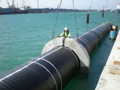
Owner was pushing to recover the time lost due to the weather and
the main contractor requested to install the ballast also at mid and
end of the string.
Breaking noises were heard after a few blocks were installed, then
the pipe broke and sunk.
Just to complete the story, after a long debate between client and
main contractor, the 3400 m long PESP outfall (luckily the pipe was 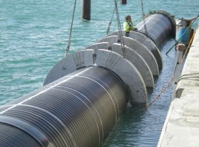
not yet produced) was substituted by a 2000 m tunnel and 1400 m of
extruded pipe.
The failure was definitely caused by the weak pipe structure and by
the type of raw material used.
Neither the installation sub-contractor nor its engineers were found
responsible; however, the debate became “political” and brought the 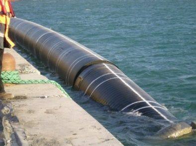
change in the design as mentioned before. The idea of substituting
the pipe with a different PESP was therefore abandoned and after
more than one year the 1400 PEEP were installed.
The decision to change the design took about one year.
This happened in 2011 and, even though it was attempted to “cover”
the failure, the facts spread and the use of PESP got a “hit”,
particularly at national level. 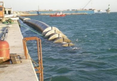
On the other side of the world, the ID 3000 of La Taboada (Lima, Peru)
was under way.
If you ask me what I think about using PESP for submarine pipelines, I
can only say that a quality pipe, whichever is its material, can be used
for underwater projects, taking into consideration, in the design and
the installation techniques, of its strengths and weaknesses.
All considered, we do not ask too much to PESP pipes…a good axial 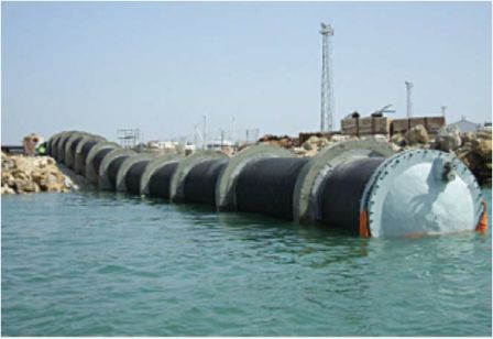
strength, a good resistance to bending, a solid jointing/welding
and the possibility of a proper ballasting.
That’s all?
Obviously, not: we must have a proper design and a reliable
contractor.
Let’s start to look at some aspects of the use of PESP in the sea.
Ballast calculation can be performed therefore in the traditional 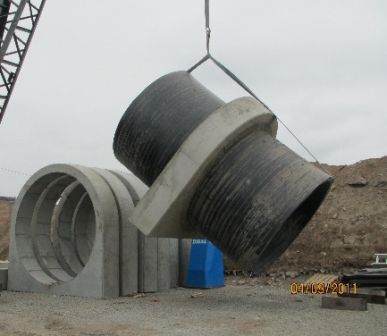
way, only assuming that the pipe’s buoyancy is very high at sinking
and will be somewhat lower after the filling of the ribs with water.
By the way, drilling 10mm holes in some of the ribs will not
endanger the pipe’s resistance.
A flat external surface – one of the “musts” for marine PESP – will
permit a safe installation of blocks, either fixing them by concreting 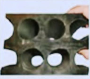
the space between block’s internal face and pipe surface (as done
in Peru) or with the traditional bolting of split collars.
The concreting of the blocs gives good results – no slippage has
been detected during a test; however the use of traditional split
collars will be in my opinion more practical.
Much will depend on the layout of the construction yard and on
the type of launching way the marine contractor chooses.
Good … we can safely install the blocks, but what else do we need, 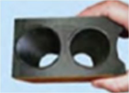
apart from the stiffness, which is the main characteristic of PESP?
Well, we expect that PESP assures sound technical characteristics
of the pipe, at least a good axial strength and a good resistance to
bending.
This can be obtained by dimensioning the single or double wall
according to the needs.
Practically, a pipe with flat external surfaces, either produced with
a finishing layer or by a solid union of the ribs can always be
considered as a double wall PESP. 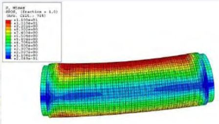
Characteristics including the bending radius
and the buckling resistance can be found by
using finite element calculations.
Since not every engineer has finite element
calculation software, there is an
approximate, but reliable way to evaluate
the pipe’s stress characteristics.
Knowing the thickness of the internal and external “wall” (or, in case of multiple layers, the
thickness of the solid layers), the “easy way” to calculate the axial strength is to use the standard
formulas applied to the “net” thickness of the wall, adopting a reasonable safety coefficient (0.85-
0.9).
It is also possible to calculate an equivalent thickness, back from the ring stiffness formula:
The = (12*SN/1000)^[1/3]
We have now the necessary values to evaluate/design the installation method:
- Pipe dimensions, weight, volume of ribs
- Pipe buoyancy
- Net wall thickness Thn to obtain the allowable axial strength
- Equivalent thickness The, from which the bending radius can be calculated
Thn and The are not the same, due to tolerances; the application of the forces shall therefore be
made on the neutral axis of the wall.
What else is needed? A good welding system, giving a weld efficiency at 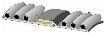
least we ˜ 1, realized according DVS 2207.
Almost all available types of jointing have been tested and used.
For ribbed and coextruded PESP, the use of bell and spigot or double bell
couplings with gasket or of the extrusion welding of pipe ends are
common, as well, in some cases, a face-to-face weld.
Nevertheless, the use of the electrowelding system has improved the 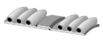
quality of the jointing for both single and double wall PESP.
Despite the efficiency of the joint, single wall ribbed pipes, while
guaranteeing a good stiffness, can reach with difficulty the characteristic
needed for a safe marine installation in terms of bending. 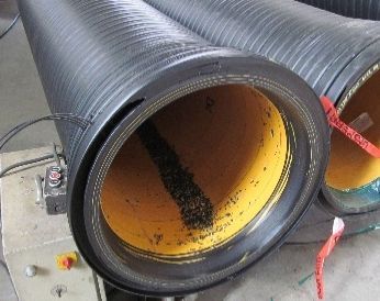
I personally consider as the safest method of welding the use of internal
and external electrowelding sectors, which guarantee both axial and
bending resistance. It has been applied with success by PPA and Krah,
which has also developed the necessary equipment
Other systems, such as the bell and spigot electro-welded joint, are equally reliable, but require more “attention” during installation.
There is a saying “You can't teach an old dog new tricks”, but in our profession it is often not true.
Keeping track of the developments, we can see that not only old tricks remain valid, but new
tricks can be learnt (or developed).
On the other hand, clients, engineers and contractors shall “adapt” themselves to the
developments and avoid keeping themselves glued to old style designs.
To propose the use of PESP for marine projects, since their application as sealines is relatively
unknown, there are two approaches:
- To adapt PESP to the project
- To adapt the project to PESP
Seems easy, doesn’t it? … but before any successful
introduction of the product, there is still a lot to do, and may
people to convince. The mentioned approaches need both a
good professionality (and luck).
- To adapt the project to PESP means to intervene in the
planning and design stage with the Engineering Compan
and, directly/indirectly, with the Client to “sell” the
concept of using PESP in the project and to modify/supply
the necessary specifications for the purchase of the pipe.
- To adapt PESP to the project means to intervene with the
tenderer or the contractor to support him with price and
technical information in order to obtain his decision to
propose PESP to the client as an alternative
The second intervention is quite problematic, however in many 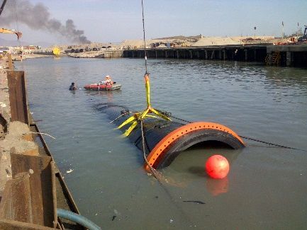
cases the project specifications are years old and are not
implemented to take into consideration the technical
developments.
Moreover, “people” are still anchored to the concept that they
may have PEEP up to 2500 and GRP up to 4000, and that they
do not need any “conversion” to PESP.
I think it will not take a long time for clients or engineers to have the “courage” to propose a PESP
ID 4000, since recent projects, including the outfalls in Peru examined hereafter, have been
realized with success.
La Taboada and La Chira outfalls, for which I was consultant for the supervisors Nippon Koei Latin
America, have confirmed my ideas that PESP installation is not so different from HDPE solid wall -
and, by the way, those techniques used for steel or GRP can be adapted to PESP.
I mention steel, since definitely most of the installation techniques derive from steel oil pipelines.
The obvious differences are in the values of the allowable stresses and moments, which are giving
the limits for the pulling forces and for the bending radius.
In practice, we have to install our pipe bringing it to the bottom 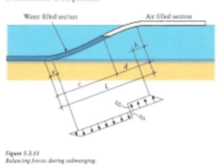
without causing a buckling. This means, just to give a rough idea
of the ratio R/ND for different materials, that the allowable
radius of curvature may be for steel 1000 x ND, for PESP roughly
200 x ND, for solid wall PEEP 50 x ND, but the shape of the “S”
sinking bend is practically the same.
Differences are the presence of buoyancy tanks, of filling, air
control, etc. 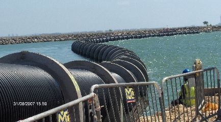
The pipe “resistance” – meaning the ensemble of characteristics
governing its application – gives the input data for designing the
installation.
Input data of the pipe are dimensional (diameter, thickness), physical (density, weight, buoyancy)
and mechanical (allowable axial and bending stresses)
On the other hand, the data on the installation environment (water density, depth, wave and
currents) give the limits for marine application.
All the above data are available when the project location and pipeline length are defined and the
pipe has been chosen for the project, either during the engineering phase or during the tendering
or contracting phase.
Once it has been agreed to the pipe choice, the installation method may/shall be identified or
recommended by the design engineers and pipe engineers for the project or proposed by the
marine contractor.
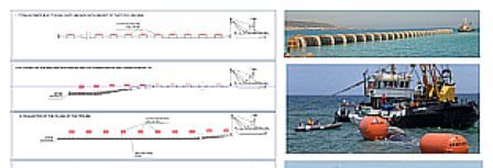
There are multiple types of installation:
• Surface tow and sink in short sections keeping the line horizontal while lowering
• Surface tow and “S” sinking, short or long sections
• Sub-surface tow and sinking as above
• Off-bottom tow and laying on the bottom
• Lay-barge method
What else? Be clever, just flood and sink … and hope, as it may happen with inexperienced
contractors… All the methods mentioned before are equally valid.
General information on the methods and the related formulas are given at
https://plasticpipe.org/pdf/chapter10.pdf.
As it can be seen, the formulas are the well- known ones, with the 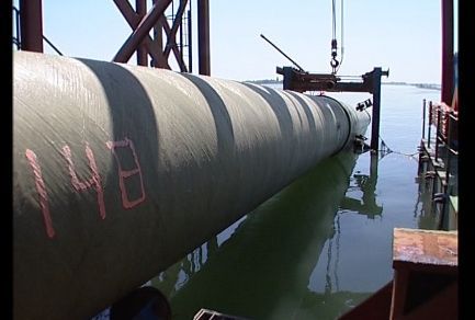
difference that we shall use an “equivalent thickness”.
Among the methods, the off-bottom and the on-bottom tow are
clearly applicable, but until now they have remained on paper at
the level of feasibility study.
For them, it is necessary to minimize the submerged weight with
buoyancy tanks and provide – if necessary – to apply the pull on
cables clamped to the pipe rather than to the pipe itself.
The picture to the right shows the idea of the lay-barge method. 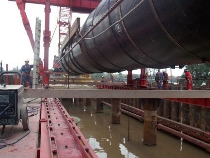
In the picture, the pipe is GRP, but the same can be done with
HDPE complete with ballast blocks.
The system may be convenient for small lines in shallow water to
avoid a duplication of the maneuvers for ballast installation and
for sinking.
It can be noted that if a large diameter pipe above 2500 is needed, 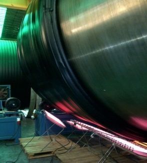
PESP production technology permits to form on mandrel a solid
wall pipe. This is an extreme (and costly) position, which can be a
marketing advantage only in countries where large diameter
extruded HDPE pipes are not available or are needed for special
projects.[In the photo, a 3600 solid wall for a project in Argentina]
What can be inferred from the first part of the paper is that we
have in our hands a good pipe – obviously keeping in mind the
differences in the mechanical characteristics – which can be
installed in the sea without major problems.
Our PESP pipe can be definitely treated – or mistreated by some improvised contractor – like a
solid wall pipe with different dimensional and mechanical characteristics, but giving, if properly
installed, the same performances.
The suitability of PESP for marine projects has been demonstrated, among others, by the Lima
projects, both as welding and installation scheme.
The two projects, La Taboada (ID 3000) and La Chira (ID 2400) 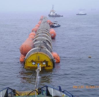
have been installed by the pipe producer PPA and Krah. This is
not a usual approach for any material, in general the SOW of
producers is limited to the supply and, in some cases, to the onsite
welding.
If a producer gets involved in a complete marine project, it may
face aspects of the project he is not aware of and also, due to the
lack of experience, to meet problems in the field, like the
trenching, in which he does not have experience or the right
equipment.
My idea is that the pipe producer shall be a “supplier” and not a
“contractor”, the only yard activity being eventually the welding or 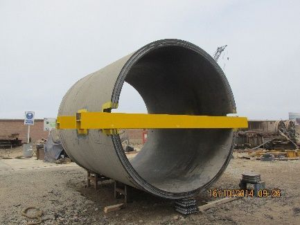
welding assistance.
On the other hand, the supplier shall be available to assist the
Clients, engineers and contractors in the design of the installation
and in the exploitation of the positive characteristics of the pipes.
I repeat what I mentioned before as a “must”: the producer shall
assist the Client in:
- adapting PESP to the project
- adapting the project to PESP
Once the project is solidly “anchored” to PESP, its realization shall
start.
By the way, let’s remember to avoid trials with corrugated PESP, in
the sea we must handle only double wall PESP with a flat surface …
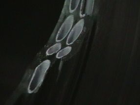
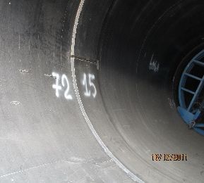
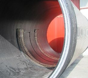
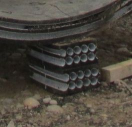
The following pictures are from the Lima Outfalls.
The structure of the wall, identical for both apart from the
thickness, is visible in the picture – 2 cut sections being used as support of the pipe element.
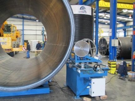
Preparation of the strings and of the launching way.
There is no substantial difference between a LW realized for PEEP or 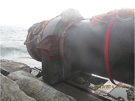
for PESP. Depending when and where the ballast blocks are installed,
the LW can be formed with rollers, rails, sleds, cars or any type of
system which will permit the translation of the string to the sea.
The LW structure type will also depend on the weight of the pipe on
top: if the ballast is installed on the ramp, it shall permit the
movement of the pipe while pulling to the sea.
In such case, the friction resistance of the moving elements shall be 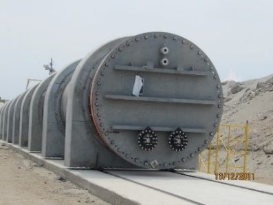
such not to exceed the axial strength of the pipe … it seems obvious,
but often the sliding element gets blocked and the pipe gets strained
if the pull is not controlled.
It may also happen – ironically – that the pipe is pushed and the end
of the string folds out as an accordion.
As far as the formation of the string, the length is set as opportune
for the installation. 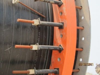
Each string ends generally with a HDPE stub-end and a free flange
(carbon steel, SS, GRP) and is closed with a blind flange with valves
for water entrance and air venting.
In this case, the pulling force has been applied to the last ballast
block, but it is recommended to provide a well designed pulling 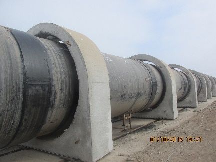
head anchored to the pipe.
The second point is related to the ballast blocks.
It shall be reminded that the apparent density will be significantly
lower than the traditional 960 kg/m3. Depending on the volume of
the voids, the net buoyancy of the pipe (External volume-weight)
can be very high. On the other hand, after the filling with water, 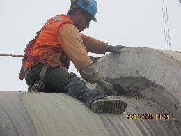
the pipe will still have a higher buoyancy than the PEEP.
It is necessary to keep in mind the difference – which may be
significant – when calculating the size of the ballast, even if it is
foreseen to fill the voids with water.
As far as the shape of the blocks, it can be referred to the ample
literature on the matter.
In Lima, the blocks have been cemented onto the pipe, after being 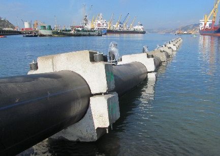
centered properly, while to the side the picture shows a traditional
split block.
A first recommendation, valid however for all pipes, is that the
blocks are heavier in the lower half than in the upper one, and that
the base is flat with or without “teeth” which will contribute to the
stability against drag forces.
The second, particular for PESP, is that the length of
the block is such to include several voids and to
round-up and protect with rubber the edges of the bock to avoid the possibility that they “cut”
into the wall.
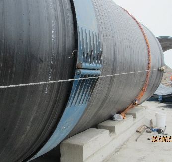
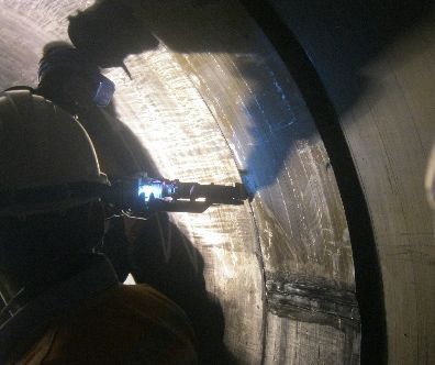
• Third item is the welding
It has been mentioned before that there can be several methods 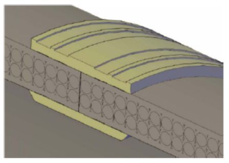
of welding double wall PESP.
As of today, we can have a face-to-face welding, bell and spigot
connection (with electrofusion) and connection with internal and
external electrowelding elements as made in Lima and as shown
here.
While for the FF welding and for the B+S a modification of the pipe
ends is required, which slows the production, for the 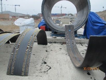
electrowelding with elements no change in the pipe structure is
required. Conceptually, this is equivalent to a double bell welded
coupling.
My personal opinion is that this method is the more suitable for
marine installations, since it guarantees a welding factor f >> 1.
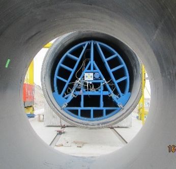
It is important to have the necessary machine to compress the elements to the pipe ends, both inside and
outside, and to enhance the tightness by extrusion-welding the element’s edges.
At this point, with the pipe on the ramp, the contractor shall decide how to launch and sink the pipe without
losing or breaking it.
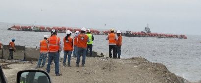
Launching
For the launching, once the pipe is ready, the ramp slope is correct, 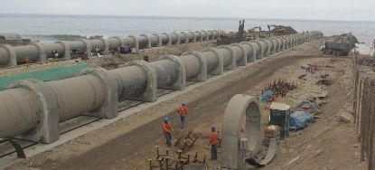
the sliding elements are checked, the pulling head is ready, etc. etc.
(meaning that all elements which may influence the operation have
been controlled) we could say that we are ready – provided that
Murphy’s Law is nod lurking – for the “easy” part.
The weather window is nevertheless important, since the waves will 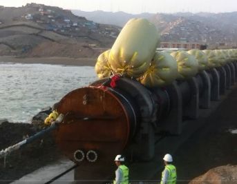
disturb the pull, causing jolts of the pipe which can damage the ramp
and pipe, and elastic behavior of the pulling cable, with the
alternation of tensions and slacks. It goes without saying that the
trench shall be ready and clean before the installation, or the bottom
profile shall have been controlled for exposed rocks or
counterslopes.
At the end of the pull, we have our pipe floating offshore ready fo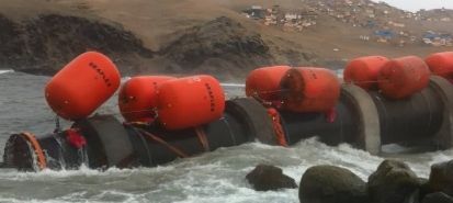
the installation.
Unless there is the risk of storms, the strings can be secured by a
tugboat or with anchoring in shallow water in a sheltered area.
Emergency safeguard operations shall be planned however if a
sudden storm or high seas are announced.
The recent weather modifications have made actual the possibility of
extreme waves or even of winds above 100 km/hr. or tornados near
the coast. 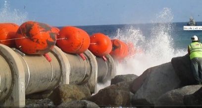
Finally, the pipe shall be floated to the position for the installation.
The contractor at this stage MUST have decided its installation plan,
by choosing the method of sinking, the need and the type of
buoyancy tanks or floaters, the necessary equipment, the diving 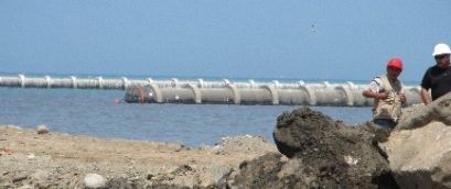
support and all other aspects of the works.
Above all, the work and safety procedures shall have been presented
with an induction meeting to site management and staff. The safety
for all underwater operations will be essential.
If we look at past projects, the use of “buoyancy tanks”, ether rigid or inflatable, is a common
aspect for the installation of almost all materials.
They have been and are used on steel, thermoplastics, rubber hoses, GRP and on any “heavy”
item to be floated on or lowered under water.
There is a longstanding debate between the use of rigid buoyancy tanks and air filled floaters.
The rigid floaters maintain their uplift value regardless of the depth, provided that the body is
designed to resist to the external pressure of the water column.
The lifting capacity of the air filled floaters (round or sausage-shaped) depends instead on the
equilibrium between external pressure and volume. Due to the compressibility of the air, the
floater volume decreases about 45% with the immersion to -10m.
It means that the floaters shall be re-pressurized to the original volume or that the sinking is
designed keeping into consideration the loss of buoyancy with the immersion.
In any case, depending on depth, a step-by-step sinking can be used.
Looking to the installation of PESP, it can be seen that, in general, the most significant aspect is
the use of buoyancy tanks or floaters to reduce the submerged weight during filling, instead of
the use of the traditional air volume control.
Once the contractor understands the function of the buoyancy elements, he shall decide for rigid
or inflatable ones, taking into consideration that the buoyancy of inflatable ones decreases with
the depth.
It has been mentioned before that PESP could be installed in various ways. For several of them,
the calculations and the verification of the possible scenarios have been derived, with the
necessary differences, from steel or PEEP projects.
Up to now, the off-bottom pull has been studied and has resulted feasible, giving also the
possibility of installation under the typical limit of air-diving depth at -40/-45m.
While it could be considered “safe” if well designed, it appears that no contractor has had the
“courage” to apply the method.
The methods which I consider safe are the “parallel sinking” and the traditional “S” sinking, either
with or without air control.
The parallel sinking is the simplest way, it does not involve particular stresses on the pipe and the
strings can be positioned with precision on the bottom if guided with the “help” of underwater
blocks.
Depending on the string length, one or two main crane barges, tugboats for the lateral control
and a sufficient number of lifting points, i.e. rigid buoyancy tanks and intermediate suspension
barges to keep the spans within tolerances and to assist in the lowering.
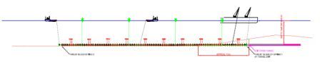
The pipe is filled keeping it suspended with one end high until the air is vented and the pipe is
full, then it is lowered by releasing the holding cables.
Finally, the buoyancy tanks are recovered for the installation of the following string.
The main problem can be the lack of control in an intermediate suspension or strong underwater
currents displacing the pipe. The guide blocks also give a means to safely perform the connection
with the flanges.
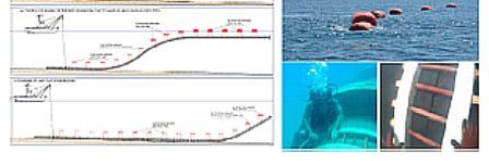
The second style is identical to the PEEP “S” sinking. In this case, a good equilibrium between
ballast and rigid buoyancy tanks shall be found,
The picture shows the connection of the two strings above water and the following sinking with
the control of the stiffened flanged connection.
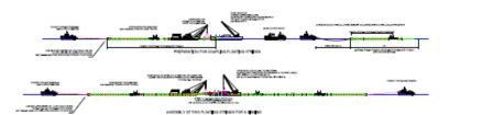

What changes in respect of the PEEP sinking is the need to keep the bending radius and the spans
within well calculated limits, depending on the lower values of axial and bending strength of PESP
in general. Also, the PESP structure can be more easily subject to surface wrinkles which may lead
to buckling.
This can be obtained with rigid buoyancy tanks., and it can be applied with very limited risks to a
depth -10/-12m, while it is still feasible down to -20/-25m with a good coordination of the
operation.
It should however be avoided in the presence of strong underwater currents, to which any large
diameter pipe is very sensitive.
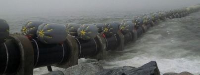
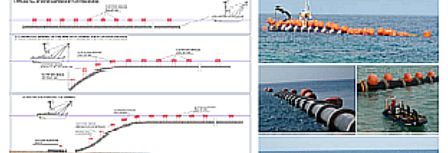
The method adopted for the Lima outfall is what can be defined as a stepped “S” sinking with
buoyancy control.
The pipe is equipped with inflated floaters and brought into position.
The sinking process is well 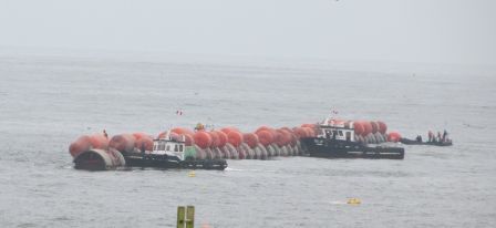
shown in the following
sequence, courtesy of PPA and
Krah and Increa.
The first step is to sink the string
to a depth of -8/-10 at pipe axis,
keeping the floaters at the
necessary pressure to have the
required buoyancy.
Further on, the first floaters are
deflated, permitting the start of the sinking of the string tail.
By regulating the pressure in the floaters, the sinking is kept under control until the pipe sits on
the bottom.
In Lima, the string ends were joined on the bottom with a normal end-to-end flanging.
A similar procedure can be realized by keeping the floaters at the surface and lowering the pipe
by progressively releasing the holding straps.
This is a combination of the “parallel sinking” and of the “S” sinking.
What about some formulas to define the launching procedure?
In the normal practice, there is no special formula … we shall refer to the normal  structural engineering’s formulas with different degrees of sophistication.
The easiest way is to use the formulas for a beam with given supports, either
fixed or elastic; the second step is constructing a sequence of configurations in
time-lapse, like the known Zentec sinking envelopes, which combine the weight
distribution and the eventual surface tension (pulling forces).
The most sophisticated system is using a complex 3D stress analysis.
Theoretically it should be the safest method of calculating the pipe behavior for sinking, but it
shall be reminded that any analysis is valid as far as the input data are valid.
Since in the sea the input data are variable on an instant base – ok, let’s say “frequently” to avoid
exaggerations -I tend to be practical: the more sophisticated and precise the input data are, the
more the probability exists to obtain a worthless calculation precise to 10 decimals, but with a
safety factor well greater than the usual 1.1-1.2
A combination of a 2D stress calculation and of proper equipment to control the sinking process
will be sufficient to execute a proper installation, provided that the pipe presents precise physical
and mechanical characteristics.
Returning to the start, we have mentioned that the first step is either to adapt PESP to the project
or to adapt the project to PESP.
It is therefore necessary to modify the Client’s way of thinking.
Either the Client does not know PESP or is contrary to it, and thinks that PESP is a good sewer pipe
whose positive characteristic is the stiffness, or, except in few cases, his opinion – maybe coming
from a bad experience – is that PESP has not the “quality” to replace solid wall HDPE or GRP.
It is worthwhile to mention to him that any type of pipe, including steel, PEEP or GRP, may similarly
not have all the necessary characteristics for an underwater installation.
Nevertheless, they can be installed, if the project requires, but none of them will be installed with
the same techniques used for more “solid” pipes.

Then, why not PESP?
At the end of the discussion, Clients, engineers, producers and contractors shall realize that they
have in their hands some 50 + years of background experience in thermoplastic materials and all
the adequate standards, values and formulas to calculate the behavior of any type of pipe,
including PESP.
All parties involved in the project shall contribute to the success of PESP marine projects: the
engineer with a safe calculation, the producers by assuring an adequate resistance to axial and
bending forces and a reliable value for the maximum radius of curvature, the contractor choosing
a reliable, safe and fail proof installation system. It’s then in the scope of work of the contractor
to apply such values to its calculations for a safe installation technique.
The best suggestion is “think positive” …
and deflect any trial of Murphy’s law disrupting the project
We must transform into an asset what others may consider a defect, and rely on a good production
technology and on the proper support too of “practical engineering” to realize the project to the
client’s satisfaction.
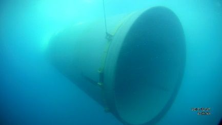
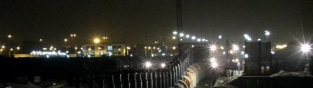
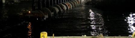
To conclude, a good night photo of the Taboada diffuser, marking the satisfactory conclusion to
a structured pipe project.
It is easier to ask forgiveness than to ask permission … mostly when time is short!
I am confident that our PPA-Krah friends will forgive the unrequested use of pictures of their
projects.
Carlo Avanzini, Dr. Eng.
