Mickey - Composite profiles
Calculation of the center of gravity (e) and moment of inertia (Ix / Jx)
Basic explanation:
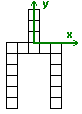
Topic: Calculating the moment of inertia of the following object.
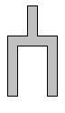
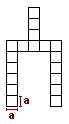
The Object has a fixed defined size and exist out of 18 squares with a side length of “a”. It is a complex objects and has a complex geometry. We can reduce the complex geometry to 4 basic rectangular objects.
Calculation center of gravity (e)
To calculate the moment of inertia we have to calculate first the center of gravity.
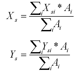
The position of the center of gravity in X- and Y-direction is the sum of products of the center of gravity position from the single components Xsi / Ysi multiplied by the area according to the single components divided by the area of the complete object.
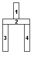
For the calculation of the center of gravity we have to define the point of reference. For example we place the point of reference in the lower left corner and we have all coordinates in the positive coordinate area. In this sample calculation we set the point of reference (point 0;0) of the coordinate system between part 1 and part 2.
We need now the position of the center of gravity of each part and the area and even the product of both. These values are easily to take out of the drawing and calculate. To get it more clear we place all the values in a table.
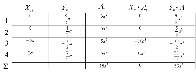
With this tabular form we have a god and clear order and under each column the sum of the necessary values. We can use these values for our calculation and place them in our equation for the center of gravity.
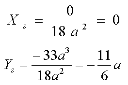
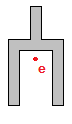
Our result is the center of gravity in position (0; -1.83). To get it more visual we place the center of gravity inside or sketch.
Calculation of the moment of inertia
The complete object is a combination of four parts.
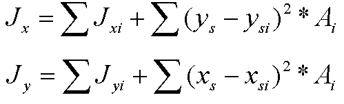
The moment of inertia for the complete structure is not only the sum of the moment of each object it is even the distance of the center of gravity of each object and the center of gravity of the complete structure / object.
The distance is squared and multiplied with the according area.
Jx = Moment of inertia, rotating around the X-axle
Jy = Moment of inertia, rotating around the Y-axle
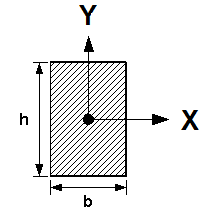
For the calculation of the moment of inertia of each single object with the know geometry we use the “Steiner“ theorem (parallel axis theorem). The four single objects are rectangles. In this case we use the equation to calculate the moment of inertia with the rotation axle X and Y for rectangles.
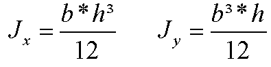
(You can use this equation only for rectangles. You can find the other equations for circles, semi circles, triangles, trapezoid, etc. in mechanical books or use the CAD calculation for complex objects!)
For this complex calculation we use a table to make it easier and more clear.
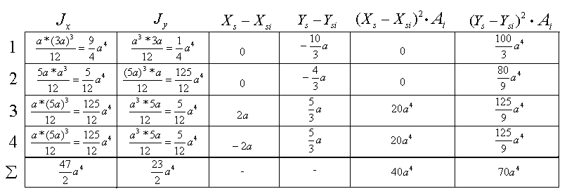
The moment of inertia will be calculated by the parallel axes theorem for the single objects. The distance results of the subtraction of the center of gravity position of the complete object and the center of gravity position of the single object.
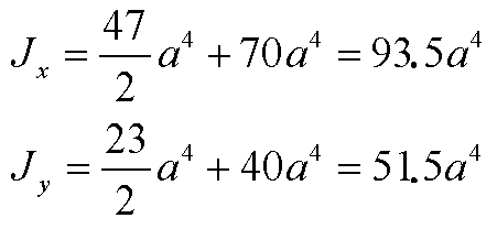
The calculated sum will be added to the equation of the moment of inertia. The moment of inertia for the rotation around the X- and Y-axle is completely calculated.
Sample for composite VW + PR-profile:
Origin-profile PR65-19.93 + VW12x140
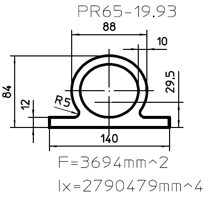 |
VW12x140 A=F=b*h = 12mm*140mm = 1680mm²
Ix=A*h²/12 = 1680mm²*(12mm)²/12 |
Coordinate system will be placed below the profile at the center axle.
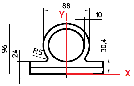
Composite center of gravity calculation:
| Xsi | Ysi | Ai | Xsi * Ai | Ysi * Ai | |
| 1 | 0 | 29.5 + 12 = 41.5 | 3694 | 0 | 153301 |
| 2 | 0 | 6 | 1680 | 0 | 10080 |
| ∑ | - | - | 5374 | 0 | 163381 |
Xs = 0mm³/5374mm² = 0mm
Ys = 163381mm³/5374 = 30.4mm
F = A = ∑ Ai = 5374mm²
Composite center of gravity calculation:
| Jx | Jy | Xs - Xsi | Ys - Ysi | (Xs - Xsi)2 * Ai | (Ys - Ysi)2 * Ai | |
| 1 | 2790479 | 0 | 0 | 30.4 - 41.5 = -11.1 |
0 | (-11.1)2 * 3694 = 455137.74 |
| 2 | 20160 | 0 | 0 | 30.4 - 6 = 24.4 |
0 | (24.4)2 * 1680 = 1000204.8 |
|
∑ |
2810639 | 0 | - | - | 0 | 1455342.54 |
Ix = Jx = ∑Jxi + ∑(Ys-Ysi)² * Ai = 2810639mm4 + 1455342.54mm4 = 4265981.54mm4
Result PR65-30.47 (Sample profile calculated with a CAD-System):
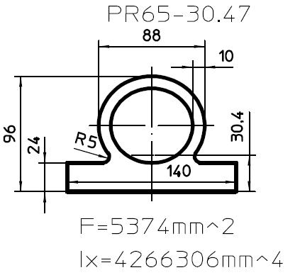
There is a minimal difference because of rounding errors from the basic drawing and the sample drawing! This will not affect further calculations (for example ringstiffness) with other programs.
Profile name generation:
PR“SD“-“XX.XX“
SD = Core tube diameter
XX.XX = IX / Profile width / 1000 = 4266306 / 140 / 1000 = 30.473614285714285714285714285714
Rounding to two decimal places = 30.47
-> Profile name = PR65-30.47
