Flanges for large diameter plastic pipes
The main task of pipe systems is to transport a medium in a safe way and without any leakage from one place to another. For polyethylene and polypropylene systems homogenous jointing connections are preferably used, as the sustainability and safety are guaranteed and they are maintenance-free as well.
Flange connections are also a very important jointing method within a pipe system, as they are a detachable connection and thus allow a transition to other pipe materials.
The main areas of applications for flange connections are:
- Connection to valves and shut-off devices
- Connection to other materials (e.g. steel)
- Connection to buildings
- Maintenance ports
- Pipe caps
- Connection to special parts and fittings
 |
 |
The bigger the pipe dimension, the less standard flanges can be found on the market. The pipe producers design the flanges professionally according to the state of art and according to the existing norms and guidelines. For pipes made of thermoplastic materials, DVS 2205 part 4 is often followed based on the AD instruction sheets B7 and B8.
Furthermore the most relevant norms provide an orientation regarding the selection of the screw quantity and the general dimensioning. Typical norms for steel flanges are, among others:
- ANSI/ASME B16.5 Class 150
- ASTM D 4024
- DIN 2673
- EN 1092
The relevant flange norms have been included for small and middle-sized diameters also in the classical plastic norms for fittings, as for example in DIN 16962 / DIN 16963.
On the basis of all these information an initial assessment regarding the dimensioning can be done. Especially regarding flange thickness, contact area, gasket etc. should be taken into account.
Before starting with the actual calculation it is helpful to make a scale drawing in order to illustrate better the proportions.
The production procedure of the flange is also very crucial for the dimensioning.
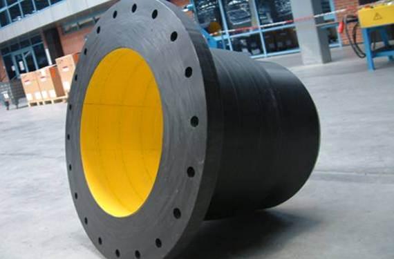
Homogenously produced flanges on basis of molded, wound (helical extruded) or axially-extruded semi-finished parts are preferable compared to welded constructions.
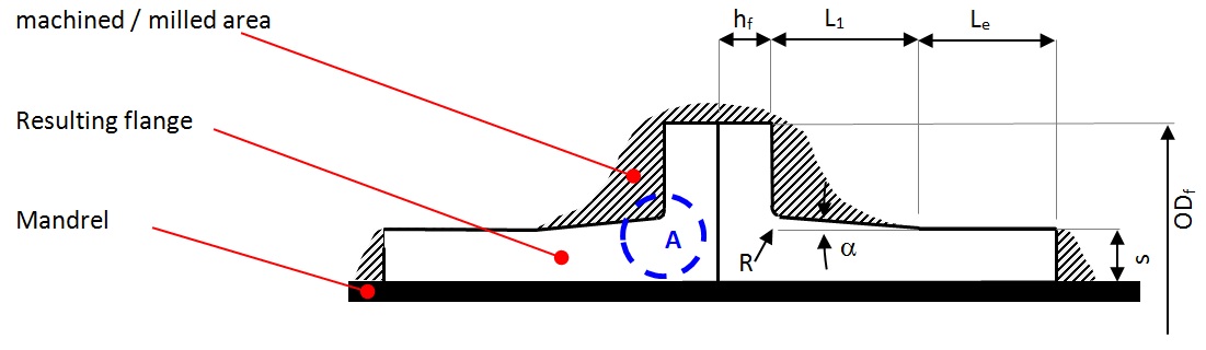
Especially for large diameter pipes the production should be carried out on a homogenously wound form and should be later machined by milling process in order to get the required shape. Thus, no extrusion seams are necessary which positively improves the strength property. The blue marked area „A“ in the sketch below is mostly loaded by bending moment and especially to be considered.
Flanges made out of a wounded pipe
(homogenous construction):
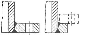
Welded flange according to DVS 2205:
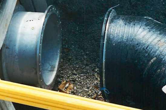
Loose-type flanges are usually built as follows:
- Stub-end made of polyethylene or polypropylene
- Loose-tpye flange made of metallic material ( optionally coated with plastic) or fiber-reinforced plastics (FRP)
Backing rings made of steel or glas fibre are often used with integral flanges due to the creep behavior of thermoplastic materials and the relatively low elastic modulus to improve the load distribution and the associated load. Thus a decoupled load situation is created and the advantages of the respective materials can be benefited from.
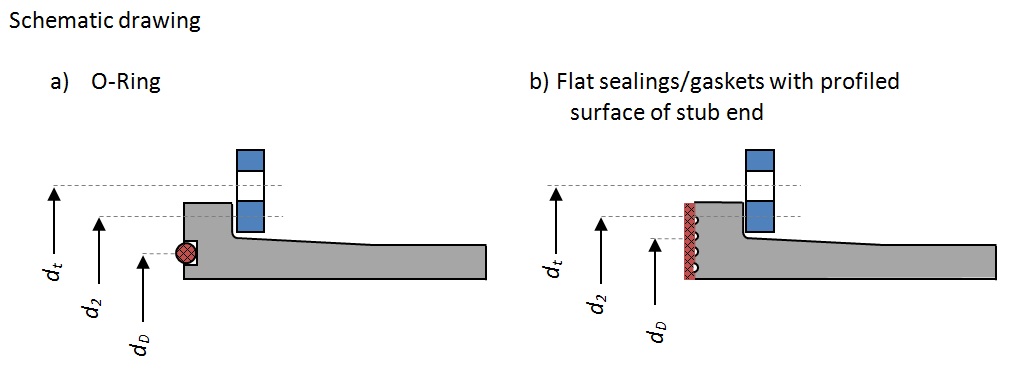
The choice of sealing material and the sealing geometry is also very important. O-ring sealings have proven themselves for plastic flanges or flat sealings/gaskets in connection with profiled surface of the stub-end. Both serve to improve the sealing effect by partially increasing the surface pressure.
Elastomer materials are principally used as sealing material – the preferred hardness generally is approx. 50-70 Shore A. When choosing the sealing material also the thermic and chemical resistance. The properties of the sealing (hardness, flexibility, etc) have a direct influence on the necessary tightening torque for the screws, just as friction and greasing between screws and nuts.
Typical values for sufficient tightening torque for M16 are for example 50 Nm...
Dimensioning of the screws:
For plastic flanges the medium distance between screw holes should not be bigger than 80 mm or
5 x diameter of holes. During the calculation it always has to be distinguished between the operating condition and the installation condition.
The surface pressure between lose flange and bund should not exceed the permissible value of thermoplastics. The same applies for the backing flanges at integral flange connections.
The necessary bolt force for flat sealings during operation is calculated as follows:
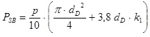
PSB = screw force during operation [N]
p = working pressure [bar]
dD = middle diameter of gasket [mm]
K1 = gasket characteristics DVS 2205-4 (material and medium - dependent) [-]
As general rule for rubber gaskets, the screw force in operation is higher as in the installation situation, however this should always be tested according to DVS 2205-4.
For O-ring sealings the position of the o-ring is crucial, resulting the formula. The groove for the O-ring should be positioned close to the pipes wall.
|
For internal flanges:
|
For stub ends:
|
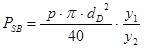
Y1 = distance between outer diameter of flange and medium diameter of pipe. Y1 (ODf - ID - s)/2
Y2 = distance between outer diameter of flange and medium diameter of screw hole circle. Y2 = (ODf - dt)/2
Dimensioning of stub end and integral type flange
The required height of stub end and integral type flange is calculated by the maximum bending moment of inertia. The moment of inertia can be calculated according following formula:
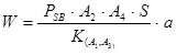
K = allowable strength acc. creep rupture curves (depending from time and temperature)
A2 = reduction factor for chemicals acc. DVS 2205
A4 = reduction factor for specific strength acc. DVS 2205
S = Safety factor
The height itself can be calculated as follows:
|
for stub ends
|
for integral type flanges
|
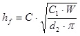
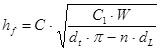
hf = Thickness flange (stub end)
C = for homogenously stub end and flanges = 0,9
for welded stub end and flanges = 1,1
C1 = for homogenously stub end and flanges = 2
for welded stub end and flanges = 3
d2 = medium diameter of contact between flange and stub end
dt = diameter screw hole circle
dL = diameter holes for srews
Furthermore should be considered:
- the angle a should be ca 15°
- the length L1 should be > hf
- at the transition from flange to pipe wall always a sufficient radius should be considered
(depends from diameter, typical values R= 5 until 10 mm)
Of course there are more details for an accurate flange design than shown in this short excursion. The most accurate results and even applicable for more complex design you can find by using finite element calculation!
For more information please don’t hesitate to contact us, we provide Engineering and Consultancy for plastic pipes Systems!
Contact:
Dipl.-Ing. Stephan Füllgrabe
Managing Director
This email address is being protected from spambots. You need JavaScript enabled to view it.
Plaspitec GmbH, Cologne, Germany
