Method for Installation of PEHD Manholes
- a technical report with 29 self-explanatory Figures -
1. HDPE Manhole & Chamber Design
PEHD Manhole and Chamber design stipulates various manufacturing configurations dependent upon actual site conditions. A number of factors including water table height, depth of cover and backfilling materials have significant impact on base configurations.
Where PEHD Manholes and chambers will be installed in areas with high ground water levels, a double bottom construction is recommended, which has to be filled with liquid concrete at the job site. In the case of the double bottom type there are two openings in the upper bottom one is for the filling of the liquid concrete and one is for the venting during the filling process. These openings need to be closed after filling and hardening of the concrete with covers. When installing the manholes up to 1200 mm diameter in ground water, for lift-retention reasons, a backfilling width of at least 50 cm is to be maintained outside and a concrete filling of the benching may be necessary.
1.1 Base Configurations:
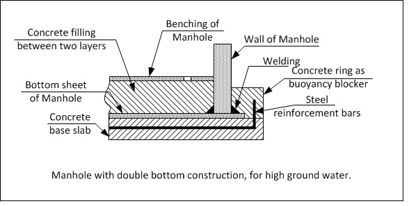
Figure 1: Manhole with double bottom construction, for high ground water
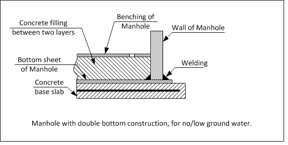
Figure 2: Manhole with double bottom construction, for no/low ground water
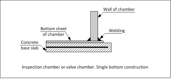
Figure 3: Inspection chamber or valve chamber. Single bottom construction
1.2 Benching Configurations:
Manhole/Chamber benching conforms to the Client’s general specifications. The Benching is fully fabricated and integrated into the Manholes/Chambers forming a complete system ready for installation.
Figure 4: Example of Typical Manhole/Chamber Benching Configuration:
1.3 General Design and Structural Calculation:
All Manholes and Chambers are designed in “Cylindrical” shape. Reducing cones are not required and eliminates a potential “Fail Point” in very deep excavations. Manholes and Chambers are designed to take full highway traffic load (HLC60) where the reinforced concrete top plate rests directly onto the Manhole/Chamber vertical wall.
For design purposes, information is collected from each site in order to provide the “Strongest & Safest” product for each individual application. Information gathered for input includes:
|
Figure 5: Krah Software |

This information, once confirmed, is then inputted into the Krah Manhole / Chamber Design Software resulting in the most appropriate product for each site and its conditions.
2. Krah HDPE Manhole/Chamber Fabrication:
The Fabrication/Manufacturing process begins after collation of the following information:
- Design Recommendations – Direct result of input data.
- Benching Configuration – From Client.
- Invert Levels – From Client
- Connection Types & Sizes (Upstream/Downstream/Backdrop) – From Client
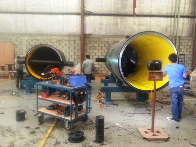
Figure 6: Krah Bahrain – HDPE Manhole Production
3. Quality Control:
Krah Bahrain is ISO 9001:2008 certified and thorough inspection and testing procedures are in place before, during and after. Some tests include:
- Hydrostatic: Each manhole/Chamber is tested for 24 hours (full of water)
- Fabrication: QA/QC Inspected
- Raw Materials: Each incoming batch.
- Finished Goods: QA/QC Inspected.
Each Manhole/Chamber delivery is inspected by the Contractor/Client before dispatch.
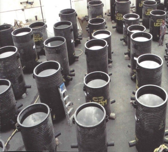
Figure 7: Krah HDPE Manholes at Hydrostatic test
4. The Installation Process of HDPE Manhole/Chamber:
4.1 Prework Requirements – For Safe & Fastest Installation Results.
- Trenching is open.
- When a water table is present, dewatering must remain constant and in place until the Manhole/Chamber is at least 80% backfilled and Top Slab is positioned.
- Precast Base Slab in accordance with Client/Krah Bahrain’s specifications.
- Precast Top Slab in accordance with Client/Krah Bahrain’s specifications.
4.2 Installing Blinding & Base Slab
- After trench excavation, install 50mm thick concrete “Blinding” in the base of the trench below where the base slab is to be constructed.
- Prefabricate the concrete Base Slab in accordance with the client’s specification. Where an “Upturn Beam” is required, a steel ring is to be cast into the base slab in order to “Key” into the “Upturn Beam”
- Position the Base Slab on top of the cured “Blinding”
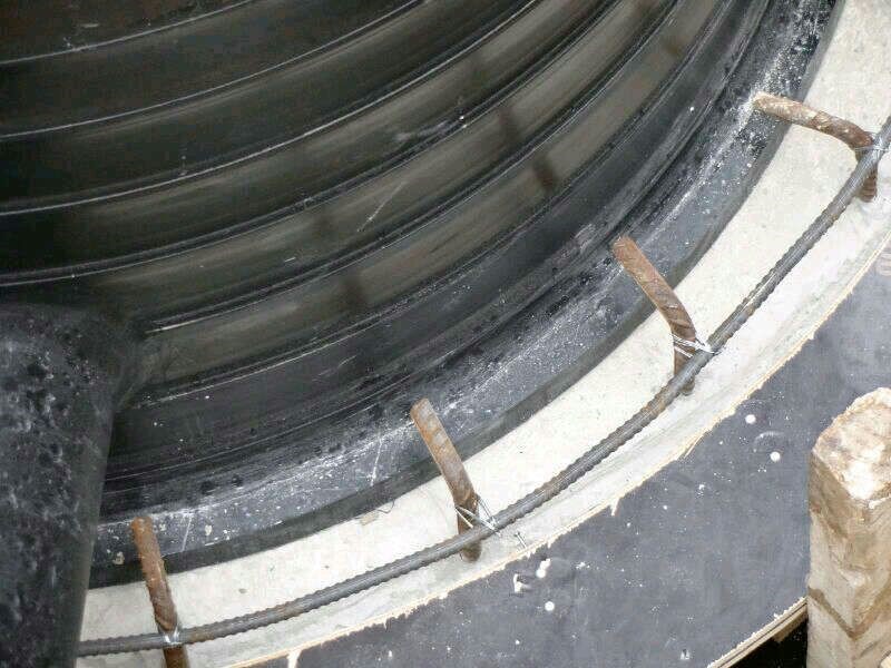
Figure 8: Krah HDPE Manhole positioned on top of precast base slab (note steel ring for “Upturn Beam’)
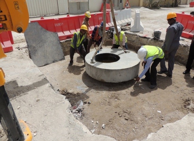
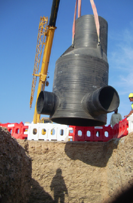
4.3 Positioning of Manhole/Chamber onto the Base Slab
- Position Manhole/Chamber onto precast base slab. Use lifting hooks for easy placement and align all connections.
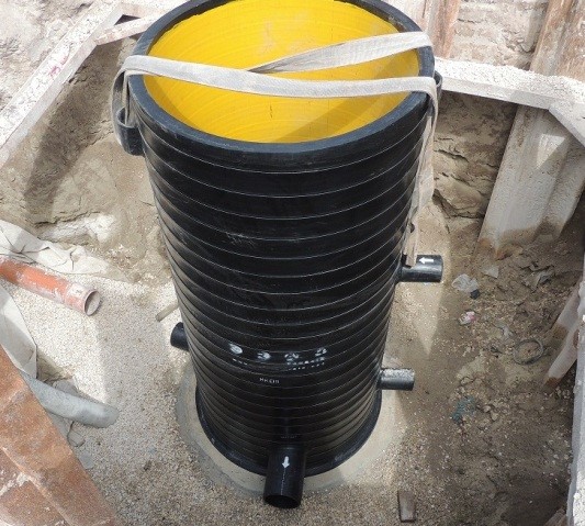
Figure 9: Krah Bahrain HDPE Manhole- Positioned onto Base Slab
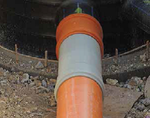
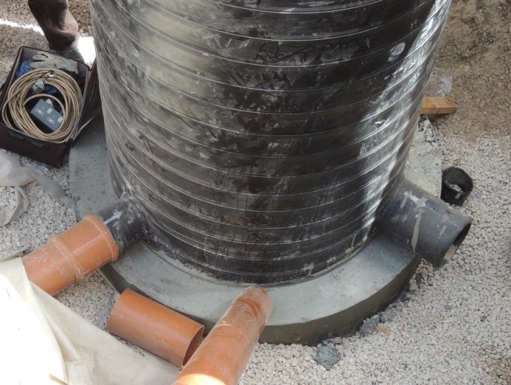
4.4 Connecting Upstream/Downstream Pipes & Backdrops
Krah HDPE Manholes and Chambers are fabricated to suit each installations requirements. All connections are made via Solid Wall HDPE pipe (in various sizes) that are fabricated into the benching of the manhole in the factory. Each connection is designed to accommodate joining to various pipe materials such as uPVC, Concrete, GRP and Vitreous Clay.
- Once aligned, connect all Upstream and downstream pipes.
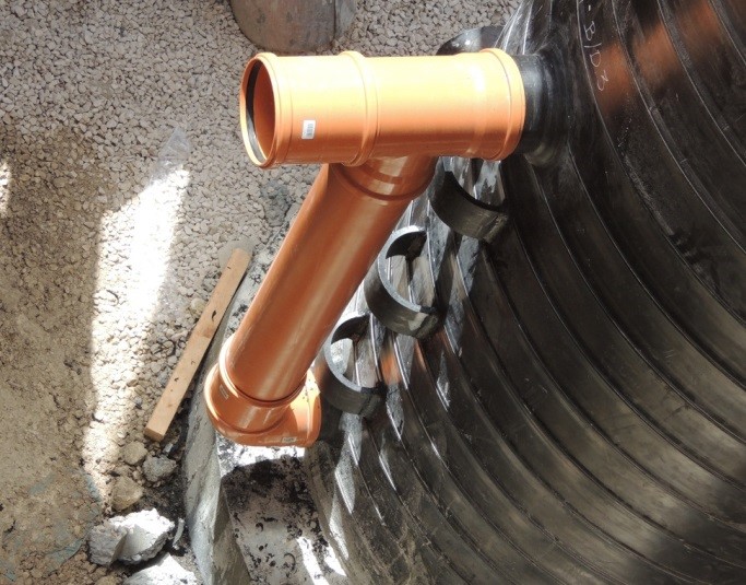
- Where UPVC connections are required, simply push the coupler over HDPE spigots. The rubber rings on the socket of the UPVC pipes match the OD of the HDPE spigot connections provided by Krah Bahrain.
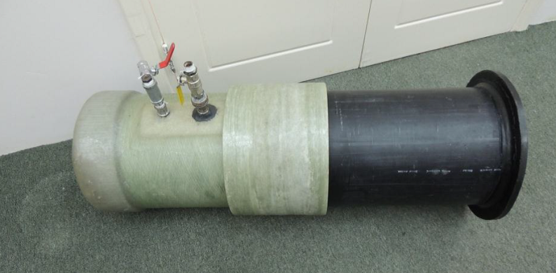
- Where GRP connections are required, specially fabricated connectors are readily available and are also compatible with the HDPE spigot connections.
|
Figure 10: HDPE to uPVC, including “Rocker Section” |
Figure 11: Krah HDPE Manhole – External Backdrop Connection with Grip Rings |
|
Figure 12: HDPE to GRP, including test unit |
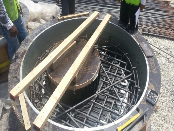
4.5 Casting “Upturn Beam” (when required)
- Construct formwork in order to cast “Upturn Beam”, holding the HDPE Manhole/Chamber firmly to the Base Slab. This is generally required when there is a high “Water Table” present and/or as recommended by Krah Bahrain.
|
Figure 13: Formwork for “Upturn Beam” |
Figure 14: Cast “Upturn Beam” |
4.6 Concreting “Benching” Internally (When Required)
- In cases of high Water Table areas, Krah Bahrain may specify “Internal Concreting” of the Benching.
- In these cases, “Access Holes” are fabricated into the benching allowing wet concrete to be poured into the internal cavity of the Benching. The “Pour Holes” will then be closed by Krah Bahrain” technicians on site. Smaller holes are provided for air release.
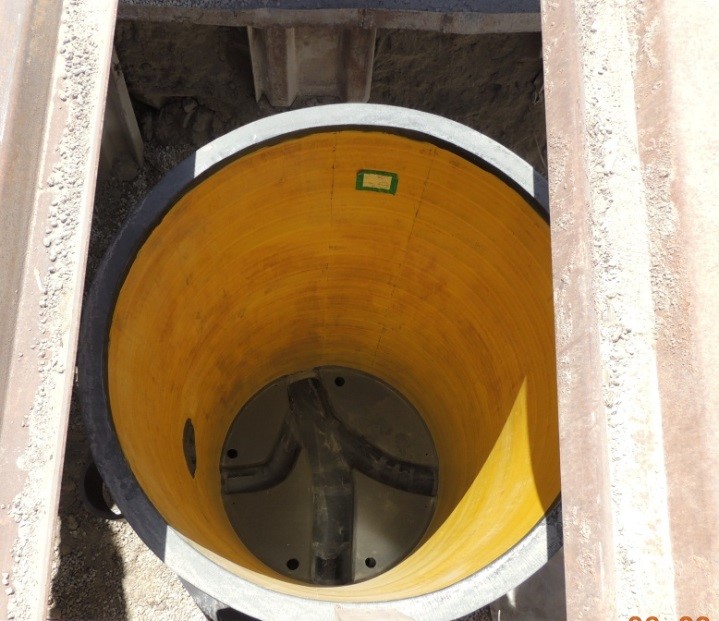
Figure 15: Access holes for pouring of liquid concrete (as required)
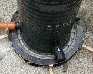
4.7 Casting in “External Backdrop” (When Required)
- Krah Bahrain HDPE Manholes/Chambers are supplied with “Grip Rings” specifically for keying/securing the concrete casting of the “Backdrop” to the main body of the Manhole/Chamber.
- Setout footing and formwork for the casting of the backdrop.
- Pour concrete and cure.
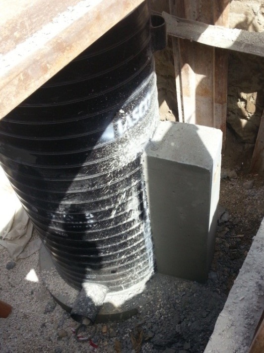
Figure 16: Cast in “External Backdrop”
4.8 Backfilling and Compaction of Krah Bahrain Manholes/Chambers
- No concrete is required in the Backfilling and Compaction process.
- Start backfilling in 300mm layers (unless specified otherwise) until reaching 80% of ground level.
- Backfilling and Compaction should, at all times, should comply with the Clients specifications and in consultation with the Krah Bahrain.
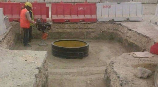
Figure 17: Backfilling & Compaction to 80% of Ground Level
4.9 Placement of Top Slab onto the HDPE Manhole/Chamber and Final Levels.
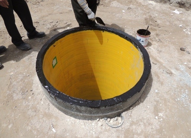
The precast Top Slab shall be lined with a “T Rib” PE liner forming a seamless transition between the Manhole/Chamber wall and the interior of the Top Slab, including the Inspection Chamber. The PE liner is fabricated in one section to suit the dimensions of each Top Slab.
|
Figure 18: PE “T Rib” Liner for casting into Top Slab |
Figure 19: Casting PE liner into Reinforced Top Slab |
|
Figure 20: Lined Top Slab |
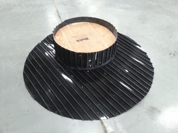
A “Non Curing” mastic sealant is then applied to the top of the Manhole/Chamber body in preparation for the PE Lined Top Slab to be positioned.
|
Figure 21: Applying mastic sealant to Manhole Top |
Figure 22: Positioning Top Slab |
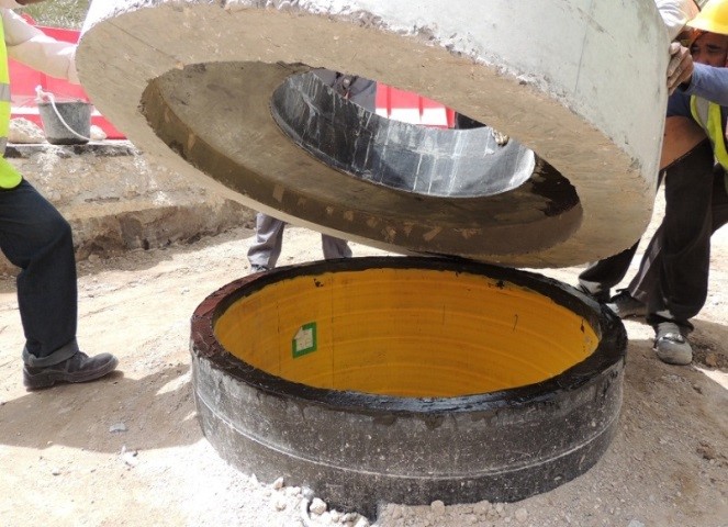
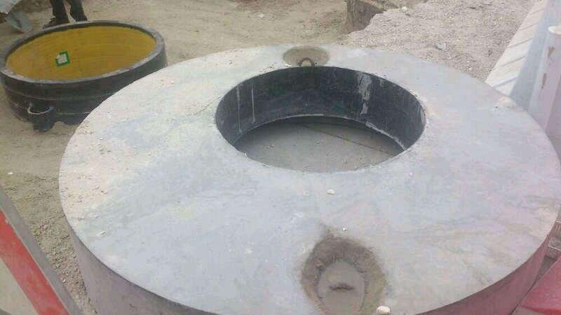
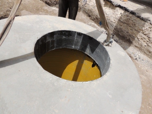
The Top Slab is then positioned onto the top of the Manhole/Chamber body and forms a seal between both parts.
|
Figure 23: Top Slab positioned onto Manhole |
Figure 24: View into Manhole |
Final backfill and compaction to pavement level can now be applied.
|
Figure 25: Ready for final road leveling |
Figure 26: Backfilled to pavement level |
5. Testing
- All “On Site” testing shall be conducted in accordance with the Client’s requirements.
- Krah Bahrain provides QA/QC test results with each delivery.
- Krah Bahrain invites the Clients representative to inspect each delivery prior to dispatch.
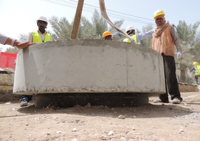
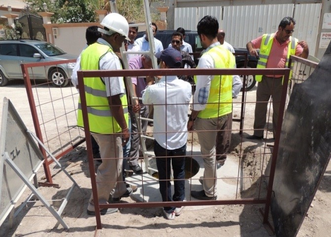
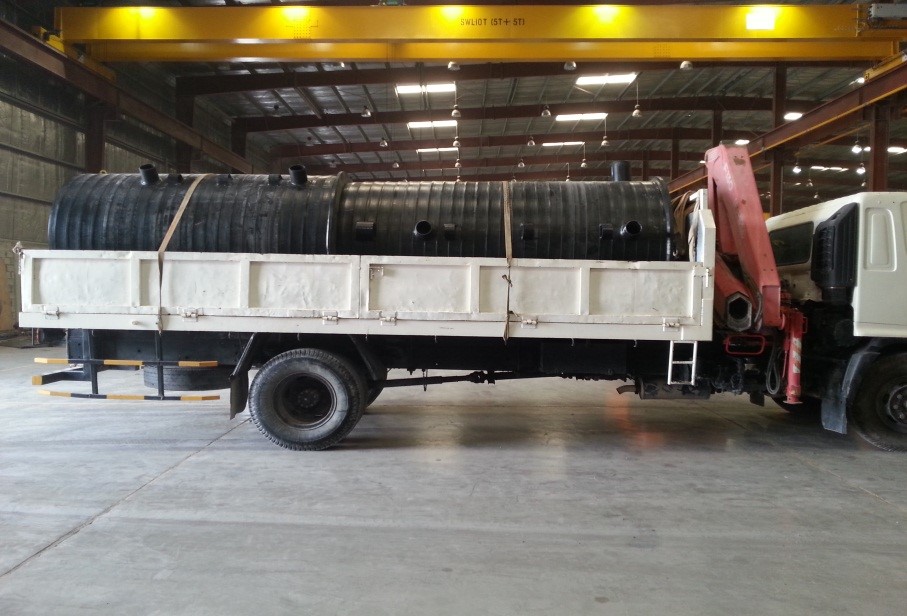
6. Handling:
- Each Krah Bahrain Manhole/Chamber is supplied with lifting lugs on either top side. Nylon Bands are recommended for lifting. Metallic Chains and Wire Ropes are NOT.
- Manholes/Chambers shall be transported laying down and fully secured using Nylon Bands and NOT Metal Chains or Wire Rope.
|
Figure 27: Handling at site |
Figure 28: Transport |
7. Storage:
- All Manholes/Chambers are to be stored on level ground and spaced appropriately enough in order to avoid being damaged.
- Krah Bahrain Manholes/Chamber can be stored externally for an unlimited time as the raw materials used in production contains “Carbon Black” giving them excellent UV protection characteristics.
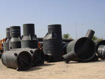
Figure 29: Storage at site