Segmented fittings fabricated from large diameter polyethylene pressure pipes
General:
Segmented Fittings are state of the art for large diameter polyethylene pressure pipe systems. The maximum injection molded bends and T-pieces are until OD 500 available, injection molded stub-ends until OD 630. In larger diameters segmented fittings are the first choice. To guarantee the required homogeneity, stability and strength it is most important to use a high quality pipe and a proper welding-technology.
Segmented fittings are used for gravity and for pressure application as well. Direct extruded and helical extruded pipes can be used, but especially the helical extruded pipes are preferred by many manufacturers, because the wall thickness can be increased easily. An increased wall-thickness is necessary to compensate weakening-factors for welding and shape of the segmented fitting.
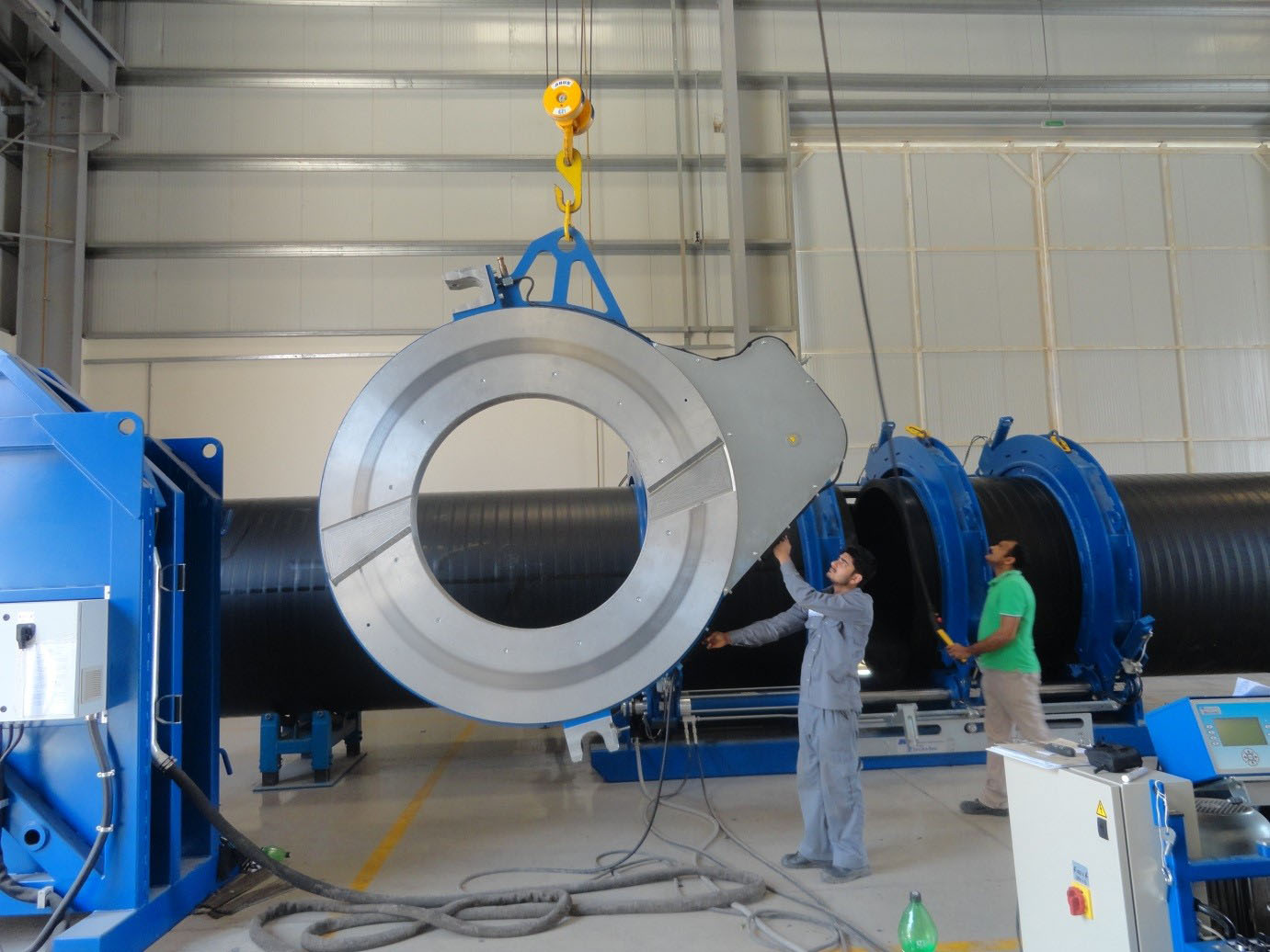
The most elegant solution for joining segments is the butt-fusion-process. The necessary butt-fusion-machines are available for PEHD-pipes until 2500 mm OD and in special cases until 3000 mm.
For butt-fusion the requirements of the standard DVS2207-1 must be considered. Furthermore for big wall thicknesses the welding parameters must be extrapolated, because the current issue of DVS 2207-1 stops at 70 mm wall thickness.
It is recommended to remove the internal welding-bead to reduce the hydraulic loss.
But there are also aspects in favor of manually joint by Extrusion-welding. For example for T-branches, with Extrusion-welding it is not necessary to cut the complete main pipe. For stability and strength, it is very advantageously that only maximum 50% of the main pipe is cut and the rest of the pipe remains untouched.
|
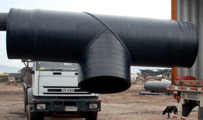
Pic 1: Butt-fused T-piece with increased wall thickness |
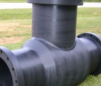
Pic 2: Extrusion welded T-branch with partially increased wall thickness |
For all segmented fittings the influence by welding has to be considered. In DVS 2205 the welding factor for short- and long-term load are mentioned:
|
Welding-procedure |
Welding-factor |
PEHD |
|
Heated Tool Butt Welding |
fz (short-term) fs (long-term) |
0,9 0,8 |
|
Hot Gas Extrusion Welding (WE) |
fz (short-term) fs (long-term) |
0,8 0,6 |
|
Hot Gas Welding (W) |
fz (short-term) fs (long-term) |
0,8 0,4 |
Table 1: welding-factors acc. DVS 2205
The loss of strength by welding and shape of segments can be compensated by a higher wall-thickness. In the Helical Extruding process (KRAH-PIPE-TECHNOLOGY), it is possible to increase the wall thickness only partly, so that the area of the branch and the welding is homogenously reinforced.
In the standard DVS 2210 are details mentioned about design of segmented fittings, especially for segmented bends. For T-branches often a finite element calculation is chosen for getting detailed results. An orientation for the weakening-factor in the area of the branch is given for example also by the German “AD-Merkblatt N1 and B9”, but it must be considered, that the equations for branches are made for not flexible pipes. So at the end, many fabricators make their design according to their experience and do pressure-tests to verify the quality.
The Pressure Test procedure for PE100 segmented fittings is described in ISO4427.
The part 3 of ISO 4427 is specially made for fittings.
 Test parameters
| Temperature | = 80 °C |
| Stress | = 5.4 MPa |
| Time | = 165 h |
Test pressure for fittings = Test pressure pipes
| Temperature | = 80 °C |
| Stress | = 5.0 MPa |
| Time | = 1000 h |
Test pressure for fittings = Test pressure for pipes
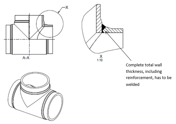
Pic.4:sketch of T-piece extrusion-welded
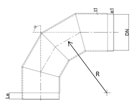
Pic 5:sketch of segmented bend 90°with increase wall thickness
e1= standard wall thickness
t1= increased wall thickness
Le= necessary length for joining-process with pipes
R = Radius
The number of segments affect the hydraulic-properties and should be chosen according E DIN 16917-1:
< 30* = 2 segments
30-60° = 3 segments
> 60° = 4 segments
Design of Bend wall thickness in 3 steps:
Step 1: general
Choice of: type of bend, radius, raw material (PE80 or PE100) and especially of the welding- procedure / production-procedure
|
Type of bend |
R |
Radius of bend |
|||
|
1,0 x OD |
1,5 x OD |
2,0 x OD |
2,5 x OD |
||
|
Seamless bends |
fBi fBa |
1,27 0,92 |
1,22 0,93 |
1,15 0,95 |
1,12 0,96 |
|
Segmented bends |
fBi fBa |
1,59 1,15 |
1,50 1,16 |
1,44 1,19 |
1,40 1,20 |
Table 1: weakening-factor acc. DVS 2210
Because of the very high radius at bends with angle up to 30° very often the weakening factor will not considered for bends until 30°. For bends with angle > 30° typically a weakening factor of 1.25 will be chosen.
Step 2: calculation of design strength
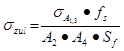
| σzul | design strength | [N/mm²] |
| σA1,3 | strength value, taken from creep rupture curves, include already influence of chosen temperature and life service time |
[N/mm²] |
| fs | long term welding factor | [-] |
| Sf | Safety factor | [-] |
| A2 | reduction ratio (chemicals) | [-] |
| A4 | reduction ratio (notch impact strength) | [-] |
Step 3: calculation of needed wall thickness
|
Bend inside:
|
Bend outside:
|
| p | inner pressure | [bar] |
| OD | outside diameter pipe | [mm] |
| σzul | design strength | [N/mm²] |
| fBi | design factor for bend inside | [-] |
| fBa | design factor for bend outside | [-] |
| Smin | minimum wall thickness | [-] |
UGPM Oman is one of the leading plastic pipe producers in the Middle-East and provides polyethylene pipes and fittings until ID 4000 mm. The fittings are manufactured under high quality aspects and Extrusion-welding as well as Butt-fusion will be used. The butt-fusion machines UGPM has installed are able to weld fittings until ID 2000 mm!
Authors:
|
|
|
 Eng. Mohammed Al Hashani
  Dipl.-Ing. Stephan Füllgrabe
